
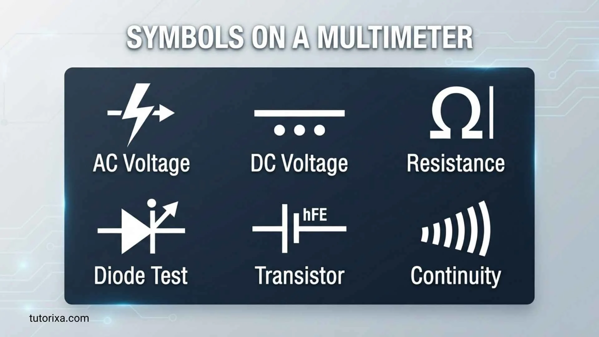
A multimeter can look confusing at first because its dial, screen, and buttons are covered with symbols rather than plain-language instructions. The symbols on a multimeter tell you what the instrument can measure, how electricity should be tested, and which settings require special care. Once you understand symbols such as V, A, Ω, continuity, diode, AC, and DC, reading a multimeter becomes much easier and safer.
You may encounter these symbols on digital multimeters, analog meters, automotive testers, electrical tools, and professional instruments. While manufacturers sometimes use slightly different icons, the underlying electrical meanings are generally standardized. Learning these symbols helps you select the correct measurement mode and understand the value displayed on the screen.
Quick Meaning
The symbols on a multimeter identify different electrical measurement functions and operating modes. Common examples include V for voltage, A for current, Ω for resistance, a sound-wave symbol for continuity, and a diode symbol for diode testing. Additional markings distinguish AC from DC, milli- and micro-units, capacitance, frequency, temperature, and other functions.
Symbol Overview Table
| Symbol or Marking | Primary Meaning | Category | Common Usage | Modern Meaning |
| V | Voltage | Electrical | Measuring potential difference | Volts |
| V~ or AC V | Alternating voltage | Electrical | Household AC circuits | AC volts |
| V⎓ or DC V | Direct voltage | Electrical | Batteries and electronics | DC volts |
| A | Current | Electrical | Measuring circuit current | Amperes |
| mA | Milliampere | Electrical | Small current measurements | Thousandths of an ampere |
| µA | Microampere | Electrical | Very small currents | Millionths of an ampere |
| Ω | Resistance | Electrical | Testing resistance | Ohms |
| Continuity icon | Continuity test | Electrical | Checking an unbroken circuit | Audible/visual continuity |
| Diode symbol | Diode test | Electronics | Testing semiconductor diodes | Forward-voltage measurement |
| F | Capacitance | Electronics | Testing capacitors | Farads |
| Hz | Frequency | Electrical | Measuring AC frequency | Hertz |
| °C / °F | Temperature | Measurement | Temperature probes | Temperature measurement |
| NCV | Non-contact voltage | Electrical safety | Detecting nearby AC voltage | Voltage detection without direct contact |
| HOLD | Display hold | Meter function | Freezing a reading | Retains displayed value |
| COM | Common terminal | Connection | Black test lead | Reference/input terminal |
| mV | Millivolts | Electrical | Very small voltage | Thousandths of a volt |
What Do the Symbols on a Multimeter Mean?
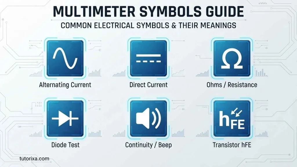
The symbols on a multimeter identify the measurement type, electrical quantity, unit, or special function selected on the instrument. The most important markings are voltage (V), current (A), resistance (Ω), continuity, diode testing, capacitance, and frequency.
A multimeter works by comparing electrical conditions at its test leads and displaying the resulting measurement. The dial tells the meter what kind of measurement to perform, while the input terminals determine where the test leads should be connected.
Understanding both parts is important. Selecting the correct dial position but plugging the red lead into the wrong terminal can produce an incorrect measurement or create a dangerous situation.
V — Voltage Symbol
The letter V represents voltage, measured in volts. Voltage describes the electrical potential difference between two points.
A meter may show separate settings for AC and DC voltage. DC voltage is commonly represented by a solid line over a broken or dashed line, while AC voltage is represented by a tilde (~).
For example:
- V⎓ or a similar line-and-dash marking = DC voltage
- V~ = AC voltage
- mV = millivolts
A battery normally provides DC voltage, while electrical outlets generally provide AC voltage.
A — Current Symbol
The letter A represents electrical current in amperes, commonly called amps.
Unlike voltage testing, current measurement usually requires the meter to become part of the circuit path. This is why multimeters often provide separate current terminals.
Common current markings include:
- A = amperes
- mA = milliamperes
- µA = microamperes
The appropriate terminal and current range depend on the meter and the circuit being tested. Always follow the meter’s instructions before measuring current.
Ω — Resistance Symbol
The Greek letter Ω, called omega, represents resistance measured in ohms.
Resistance indicates how strongly a component or material opposes electrical current. A resistor, heating element, wire, fuse, switch, or other component can have its resistance checked with this setting.
Resistance measurements generally require the circuit or component being tested to be de-energized. Measuring resistance on a powered circuit can produce incorrect readings and may damage the meter.
Continuity Symbol
The continuity function is usually represented by an icon resembling sound waves, a speaker, or a diode-like symbol combined with sound-wave markings. The exact design varies by manufacturer.
A continuity test checks whether an electrical path is sufficiently complete for current to pass through. When continuity is detected, many digital multimeters produce an audible beep.
This function is useful for checking:
- Wires
- Switches
- Fuses
- Connectors
- Circuit traces
- Cable connections
Continuity does not mean that a component is automatically good. A wire may have continuity but still have excessive resistance, and a circuit may require more detailed testing.
Diode Symbol
The diode-test function commonly uses the standard schematic symbol for a diode: a triangle-like? No—the standard diode symbol consists of a triangle-free arrowless shape with a triangle-like visual in some simplified depictions, but on electrical schematics it is more accurately represented as a triangle-free diode symbol consisting of a triangle-free filled? The safest identification is the familiar diode symbol with a triangle-free diode body and vertical bar.
The meter’s diode mode typically applies a small test current and displays the voltage drop across the diode. This helps determine whether a semiconductor diode behaves normally in its forward direction.
Because diode symbols can be difficult to recognize on compact meters, checking the manufacturer’s manual is useful when several functions share one dial position.
Capacitance Symbol
Capacitance is commonly represented by F, the unit symbol for farads, or by an icon resembling the two plates of a capacitor.
Typical values are:
- F = farads
- mF = millifarads
- µF = microfarads
- nF = nanofarads
A capacitance function is used to estimate the capacitance of a capacitor. Capacitors should be properly disconnected and discharged according to safe procedures before testing.
Hz — Frequency Symbol
Hz represents hertz, the unit of frequency.
Frequency measures how many cycles occur per second. A multimeter with a frequency function can measure signals from electrical or electronic systems within the meter’s specified range.
For example, a reading of 60 Hz indicates 60 cycles per second. The actual frequency capability varies considerably between multimeter models.
Temperature Symbols
Some multimeters include °C and/or °F settings. These indicate temperature measurement using a compatible temperature probe or thermocouple.
Temperature measurement is common in:
- HVAC work
- Electronics
- Automotive diagnostics
- Electrical maintenance
- Appliance troubleshooting
Never assume that a generic temperature probe is compatible with every meter. The probe type and temperature range should match the meter’s specifications.
History and Origin of Multimeter Symbols
The symbols used on multimeters developed from broader electrical and engineering notation rather than from a single ancient symbolic tradition. Modern multimeters combine standardized scientific units, schematic symbols, abbreviations, and manufacturer-specific interface icons.
The development of electrical measurement accelerated during the 19th century as scientists and engineers established practical systems for describing voltage, current, resistance, and other quantities. The work of figures such as Georg Ohm, André-Marie Ampère, and Alessandro Volta contributed to the terminology and units now familiar to electrical engineers.
The ohm is associated with Georg Ohm, the ampere with André-Marie Ampère, and the volt with Alessandro Volta. These names became embedded in the International System of Units and eventually appeared in compact forms on electrical instruments.
Portable meters later combined several instruments into one device. The term multimeter reflects this ability to perform multiple measurements, including voltage, current, and resistance.
As digital multimeters became widespread, manufacturers needed compact visual controls. Letters such as V, A, and Ω were combined with graphical symbols for AC, DC, continuity, diode testing, capacitance, and other functions.
Symbolism and Interpretation
Unlike cultural symbols such as religious signs or national emblems, multimeter symbols are primarily functional technical notation. Their purpose is to communicate information quickly rather than represent cultural beliefs.
The most important distinction is between symbols that identify a quantity and symbols that identify a mode.
For example, Ω identifies resistance, while a continuity icon identifies a testing function. Similarly, V identifies voltage, while the AC or DC marking specifies the type of voltage being measured.
Positive and Negative Interpretation
Multimeter symbols do not normally have positive or negative symbolic meanings in a cultural sense. However, they can communicate practical consequences.
A correct symbol selection can lead to an accurate measurement. An incorrect selection can produce an invalid reading and, depending on the circuit and meter, may create a safety hazard.
This makes understanding the symbols important not because they carry hidden symbolism, but because they provide instructions in a compact visual language.
Cultural Significance
Multimeter symbols have little cultural symbolism, but their design reflects the international nature of electrical engineering.
Electrical professionals across different countries can recognize markings such as V, A, Ω, Hz, and F because these are connected to internationally used units and technical conventions.
Regional differences still occur. A manufacturer may place the same function behind a different graphic icon, combine two functions on one dial position, or use different abbreviations for auxiliary features.
The underlying measurement concept remains more important than the exact artwork of the icon.
Scientific or Technical Meaning
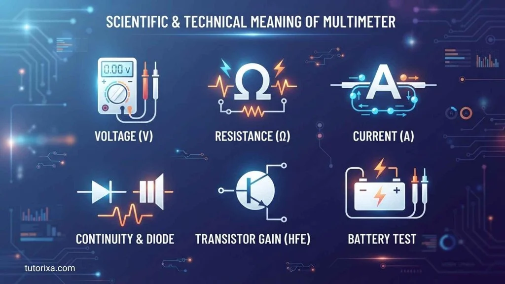
The technical meaning of multimeter symbols is central to understanding the instrument.
AC and DC Symbols
AC, or alternating current, changes direction periodically. The tilde ~ is commonly used to identify AC measurements.
DC, or direct current, maintains a consistent polarity in normal operation. A solid line above a broken or dashed line is commonly used to represent DC.
Milli and Micro Prefixes
Metric prefixes help indicate measurement scale:
- m = milli = one-thousandth
- µ = micro = one-millionth
- k = kilo = one thousand
- M = mega = one million
These prefixes matter because confusing them can lead to major errors in interpreting a reading.
COM Terminal
COM means common. It is normally the terminal used for the black test lead on many multimeters.
The red lead is moved to a different input when measuring certain quantities, particularly current. Terminal arrangements vary by model, so the meter’s markings and instructions should always be followed.
HOLD Symbol
The HOLD function freezes the displayed measurement. It can be useful when the meter screen is difficult to see while the probes are positioned elsewhere.
Some meters also provide an automatic or peak-hold function, which is different from ordinary display hold.
NCV Symbol
NCV commonly means non-contact voltage. On meters equipped with this feature, the function can detect the presence of certain nearby AC electrical fields without directly contacting the conductor.
NCV detection is generally a screening function, not a substitute for proper electrical testing. Its behavior depends on voltage, distance, insulation, conductor arrangement, and the meter’s design.
Where Are Multimeter Symbols Used?
The same basic electrical symbols appear across many technical environments.
Electronics
Technicians use voltage, resistance, continuity, diode, capacitance, and frequency functions when diagnosing electronic circuits.
Automotive Diagnostics
Automotive technicians commonly use DC voltage, resistance, continuity, and current measurements to investigate batteries, wiring, sensors, switches, and electrical systems.
Household Electrical Work
Meters can be used to measure electrical characteristics in appropriate situations, although mains electricity presents serious hazards. Only suitable equipment and safe procedures should be used.
Engineering and Education
Electrical engineering students encounter these symbols in laboratories, circuit diagrams, textbooks, and measurement exercises.
Circuit Diagrams
Symbols such as the diode and capacitor markings are related to the broader language of electrical schematics. A multimeter’s icon is often a compact reminder of the component or measurement involved.
Common Variations
Multimeter symbols vary between manufacturers and models.
A professional meter may use separate positions for AC and DC voltage, while another model may combine them under one voltage setting and use a button to switch modes.
Similarly, continuity, diode testing, and resistance may share one dial position. A dedicated button can then select the desired function.
Other variations include:
- Backlight symbols
- Auto-ranging indicators
- Low-battery icons
- Min/max recording
- Relative measurement
- Frequency/duty-cycle modes
- Temperature functions
- Non-contact voltage detection
- Low-impedance voltage modes
The exact icon should therefore be interpreted alongside the meter’s model-specific manual.
Common Misconceptions
“Ω Means the Meter Is Measuring Electricity.”
Not exactly. The Ω symbol specifically indicates resistance measurement. It does not mean the meter is generally measuring electricity.
“Continuity Means the Wire Is Perfect.”
No. Continuity simply indicates that the meter detects a sufficiently conductive path under its test conditions. It does not prove that the wire can safely carry a particular current.
“A Voltage Symbol Always Means AC.”
No. Voltage can be AC or DC. Look for the additional AC or DC marking.
“The Same Symbols Work Identically on Every Multimeter.”
The basic meanings are widely shared, but functions, ranges, terminals, and icons can differ between models.
“A Multimeter Can Measure Any Electrical Quantity.”
No. A meter only measures the quantities and ranges for which it was designed. Exceeding its specifications can damage the instrument or create a safety risk.
Interesting Facts About Multimeter Symbols
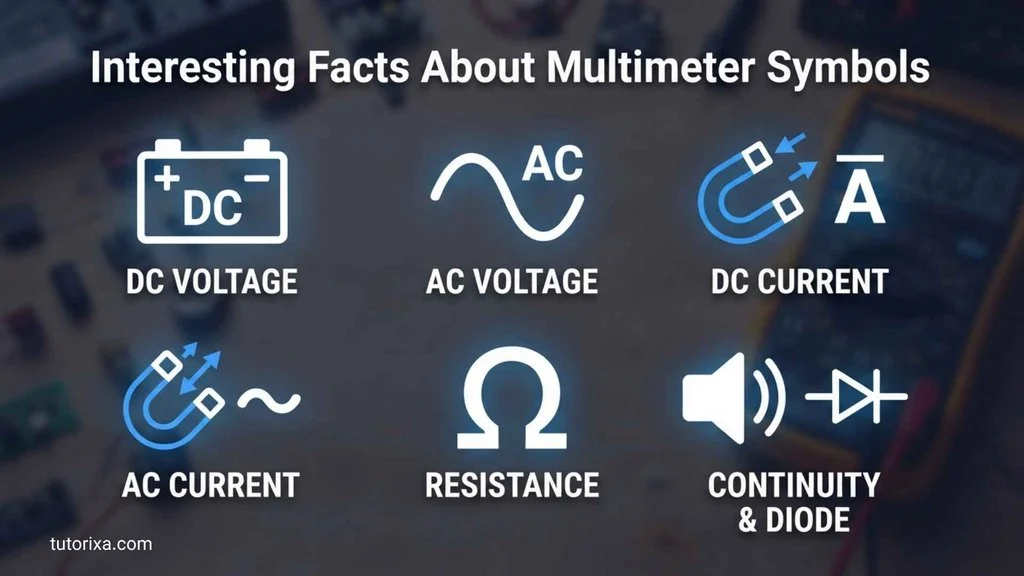
- Ω comes from the Greek letter omega.
The ohm uses Ω as its unit symbol, linking modern electrical measurement with the Greek alphabet. - V, A, and Ω represent different electrical quantities.
Voltage, current, and resistance are related but are not interchangeable measurements. - The tilde is associated with alternating quantities.
The waveform-like ~ marking provides a compact visual distinction for AC. - A continuity icon often represents sound.
Many meters beep during a continuity test, so the icon may resemble sound waves or a speaker. - A diode symbol is also used in circuit diagrams.
The meter’s diode-test marking connects instrument controls with the standard visual language of electronics. - Metric prefixes dramatically change measurement scale.
A milliampere and an ampere differ by a factor of 1,000, while a microampere differs by a factor of 1,000,000. - COM does not mean negative in every electrical situation.
It identifies the meter’s common input terminal. Polarity and circuit reference depend on the measurement. - Digital meters can combine several functions.
One dial position may control resistance, continuity, and diode testing through a separate button. - Not every meter has the same symbols.
Basic household meters may have only a few functions, while advanced instruments can include frequency, capacitance, temperature, and specialized electrical modes. - Symbols reduce the need for long labels.
A compact instrument benefits from internationally recognizable abbreviations and graphical notation.
Related Symbols
Several electrical symbols are closely connected to multimeter functions.
- V — identifies voltage.
- A — identifies current.
- Ω — identifies resistance.
- Hz — identifies frequency.
- F — identifies capacitance.
- W — identifies power, although many multimeters do not directly measure watts.
- ~ — commonly identifies alternating current or voltage.
- ⎓ — commonly identifies direct current or voltage.
- Diode symbol — identifies semiconductor diode testing.
- Continuity icon — identifies a circuit-path test.
- °C/°F — identifies temperature measurement.
These symbols form part of a much larger technical vocabulary used in electronics, electrical engineering, physics, and instrumentation.
Frequently Asked Questions
What are the most common symbols on a multimeter?
The most common symbols are V for voltage, A for current, Ω for resistance, and icons for continuity and diode testing. Many meters also include Hz for frequency, F for capacitance, and °C/°F for temperature. AC and DC markings distinguish alternating and direct measurements.
What does V mean on a multimeter?
V means voltage, measured in volts. A voltage setting measures the potential difference between two points. The meter may provide separate AC and DC options or combine them into one setting. Always select the appropriate voltage mode and range for the circuit being tested.
What does Ω mean on a multimeter?
The Ω symbol means resistance, measured in ohms. It is used to test the resistance of components, wires, and other conductive paths. Resistance measurements should normally be made on a de-energized circuit because applying external voltage can interfere with the measurement and potentially damage the meter.
What does the continuity symbol mean on a multimeter?
The continuity symbol identifies a test that checks whether an electrical path is sufficiently continuous. Many digital multimeters beep when they detect low resistance between the probes. The exact beep threshold varies by meter, so continuity should not be treated as an exact resistance measurement.
What does the diode symbol mean on a multimeter?
The diode symbol identifies diode-test mode. This function typically applies a controlled test current and measures the voltage across a semiconductor junction. It can help determine whether a diode conducts in the expected direction. The precise behavior and displayed values depend on the component and meter.
What does A mean on a multimeter?
A stands for ampere, the unit of electrical current. Multimeters may also use mA for milliamperes and µA for microamperes. Current measurement differs from ordinary voltage measurement because the meter is typically inserted into the circuit path. The correct current terminal must be used.
What do AC and DC symbols mean on a multimeter?
AC means alternating current, while DC means direct current. AC is commonly represented by a tilde (~), while DC is commonly shown with a solid line over a broken or dashed line. These markings tell you which type of electrical signal the selected measurement mode is designed to evaluate.
What does COM mean on a multimeter?
COM means common and usually identifies the common input terminal for the black test lead. The other terminals may be designated for voltage/resistance measurements or different current ranges. Terminal layouts vary, so users should check the markings on their particular multimeter before connecting the leads.
What does Hz mean on a multimeter?
Hz stands for hertz, the unit of frequency. One hertz represents one cycle per second. A multimeter with a frequency function can measure the frequency of suitable electrical signals within its specified operating range. Frequency measurement is particularly useful in electronics and certain electrical troubleshooting applications.
Why are multimeter symbols different between brands?
Manufacturers may use different graphic designs, abbreviations, button layouts, and combinations of functions. However, fundamental units such as volts, amperes, ohms, farads, and hertz follow established technical conventions. When an icon is unclear, the safest approach is to consult the specific model’s user manual.
Key Takeaways
- V means voltage and represents volts.
- A means current and represents amperes.
- Ω means resistance and represents ohms.
- The AC tilde (~) identifies alternating measurements.
- The DC line-and-dash marking identifies direct measurements.
- The continuity icon is used to check whether a conductive path is present.
- The diode symbol identifies diode-testing mode.
- Hz represents frequency.
- F represents capacitance in farads.
- mA and µA indicate smaller current ranges.
- COM identifies the common meter terminal.
- Symbols can vary slightly between manufacturers.
- Correct symbol selection is essential for obtaining meaningful measurements.
- A multimeter’s symbols are technical notation rather than cultural or religious symbolism.
- The manufacturer’s instructions should take priority when a function or icon is unclear.
Conclusion
The symbols on a multimeter are essentially a compact language for electrical measurement. Once you recognize V, A, Ω, AC, DC, continuity, diode, Hz, and capacitance markings, the meter’s controls become much easier to understand.
The most important lesson is to connect each symbol with both its electrical quantity and practical function. Voltage measures potential difference, current measures charge flow, resistance measures opposition to current, and specialized modes examine properties such as continuity, capacitance, frequency, or diode behavior.
Because multimeters differ in design, symbols should always be interpreted together with the markings, terminals, ratings, and instructions for the specific instrument. Understanding this visual language not only makes measurements easier but also helps prevent incorrect readings and unsafe use.

I’m Ellis Montgomery, a British writer interested in the powerful language of symbols. I explore everything from traditional emblems and cultural signs to contemporary symbols found in modern life. My aim is to explain their meanings clearly while revealing the stories and ideas behind them, making symbolism fascinating and accessible to everyone.
Books:
- The Complete Book of Symbols
- Hidden Messages in Everyday Symbols
 Rowan Whitaker
 Freddie Beaumont