
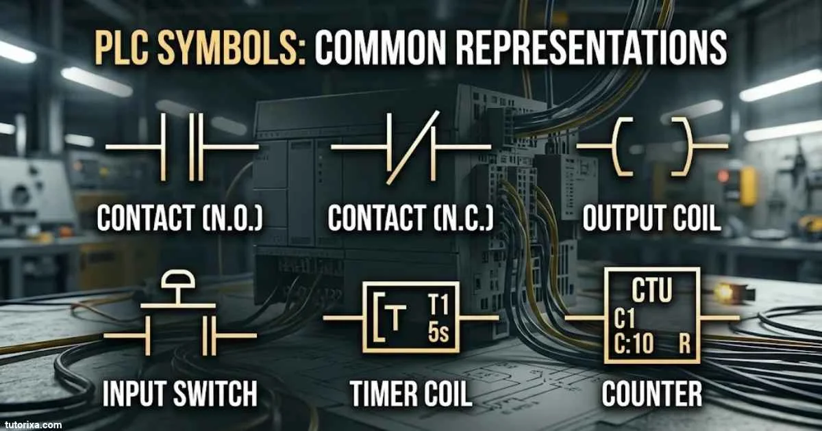
PLC symbols are used in industrial automation to represent electrical components, input devices, output devices, and control functions in programmable logic controller (PLC) systems. They help engineers, electricians, and technicians understand how a machine or automated process works without reading lengthy written instructions. Learning these symbols makes it easier to read electrical drawings, troubleshoot control circuits, and create PLC programs.
There are different types of PLC symbols, including ladder logic symbols, switch symbols, input and output symbols, timer symbols, counter symbols, and instrumentation symbols. Some symbols represent physical devices, such as push buttons and sensors, while others represent programming instructions that control how a PLC responds to different conditions.
In this guide, you’ll find common PLC symbols and their meanings, easy-to-understand charts, ladder diagram examples, and symbols used in Allen-Bradley, Siemens, AutoCAD, and HVAC control systems. You can use these references to understand PLC diagrams, identify components, and learn the basics of industrial control systems.
PLC Symbols And Meanings
PLC symbols are graphical representations of electrical components and programming instructions used in programmable logic controller systems. They provide a standard way to communicate how different parts of an automation system work together.
A PLC receives information from input devices, processes that information according to its programmed logic, and sends commands to output devices.
For example, when an operator presses a start button, the PLC receives an input signal. It processes the signal and activates an output connected to a motor starter.
Here are some commonly used PLC symbols and their meanings.
| Symbol or notation | Name | Meaning |
|—|—|—|
| —| |— | Normally Open Contact | Allows logic to pass when its assigned condition is true |
| —|/|— | Normally Closed Contact | Allows logic to pass when its assigned condition is false |
| —( )— | Output Coil | Represents an output controlled by ladder logic |
| —(S)— | Set Coil | Sets a Boolean output or bit |
| —(R)— | Reset Coil | Resets a Boolean output or bit |
| TON | On-Delay Timer | Delays an output after an input condition becomes true |
| TOF | Off-Delay Timer | Delays an output turning off |
| CTU | Count Up | Increases a counter value |
| CTD | Count Down | Decreases a counter value |
| RES | Reset Instruction | Resets supported timer or counter data |
| ADD | Addition | Adds numerical values |
| SUB | Subtraction | Subtracts one value from another |
| MOV | Move Instruction | Transfers data from one location to another |
These symbols are common examples, but their exact appearance and instruction names depend on the PLC manufacturer and programming software.
Common PLC Input Symbols
Input symbols represent devices that send information to a PLC.
| Symbol/device | Name | Common purpose |
| PB | Push Button | Sends a manual control signal |
| LS | Limit Switch | Detects a mechanical position |
| PS | Pressure Switch | Detects a pressure condition |
| TS | Temperature Switch | Detects a temperature condition |
| FS | Flow Switch | Detects fluid flow |
| PE | Photoelectric Sensor | Detects objects using light |
| PROX | Proximity Sensor | Detects nearby objects |
| E-STOP | Emergency Stop | Requests an emergency machine stop |
Common PLC Output Symbols
Output symbols represent devices controlled by the PLC.
| Symbol/device | Name | Function |
| M | Motor | Drives mechanical equipment |
| SOL | Solenoid | Operates a valve or mechanical mechanism |
| L | Indicator Lamp | Shows an operating condition |
| BZ | Buzzer | Produces an audible warning |
| K | Contactor or Relay | Switches an electrical circuit |
| V | Valve | Controls fluid or air flow |
| HTR | Heater | Produces heat |
Remember that device tags such as PB, LS, and SOL are common drawing abbreviations, not universal PLC programming symbols. Always check the drawing legend before identifying a component.
Basic PLC Symbols
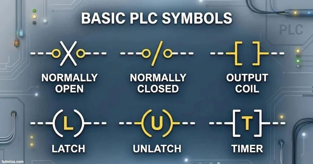
Basic PLC symbols are the starting point for understanding programmable logic controllers. They represent the fundamental components and conditions used in simple automation programs.
Most basic PLC diagrams include input contacts, output coils, connecting lines, and power rails.
Here are the basic symbols you should recognize.
1. Normally Open Contact
Symbol:
—| |—
A normally open (NO) contact represents a condition that allows logic to pass when its assigned Boolean variable is TRUE.
For example, a start push button can be represented by a normally open contact. When the button is pressed and the input becomes TRUE, the contact instruction becomes logically true.
2. Normally Closed Contact
Symbol:
—|/|—
A normally closed (NC) contact instruction is true when its assigned Boolean variable is FALSE.
It is commonly used for stop conditions, interlocks, and other control requirements.
An important distinction: an NC ladder instruction does not automatically mean the physical switch is wired as a normally closed device. The physical contact arrangement and the PLC instruction are two separate things.
3. Output Coil
Symbol:
—( )—
An output coil represents a Boolean result controlled by the ladder logic.
For example, it can operate a motor starter output when the required input conditions are satisfied.
4. Set Coil
Symbol:
—(S)—
A set coil turns a Boolean bit or output on and keeps it set until a reset operation occurs.
It is useful for latching control conditions.
5. Reset Coil
Symbol:
—(R)—
A reset coil clears a previously set Boolean bit or output.
It is commonly paired with a set instruction in control applications.
6. Connecting Lines
─────────────
Connecting lines represent the logical paths between contacts, branches, and output coils in a ladder diagram.
7. Power Rails
| |
| |
| |
The vertical rails define the boundaries of a ladder logic network. In traditional ladder diagrams, the left rail represents the starting side of the logical path.
PLC Symbols And Functions
Different PLC symbols perform different jobs. Some represent input conditions, while others control outputs, measure time, count events, or process numerical information.
Understanding their functions helps you interpret PLC programs and identify the instructions used in automation systems.
Here are the main categories.
Input Symbols And Functions
Input instructions check the status of information received from external devices.
| Symbol | Function | Example |
|—|—|—|
| —| |— | Checks whether a Boolean condition is TRUE | Start button pressed |
| —|/|— | Checks whether a Boolean condition is FALSE | Stop condition inactive |
| XIC | Examine If Closed | Allen-Bradley true-condition instruction |
| XIO | Examine If Open | Allen-Bradley false-condition instruction |
Output Symbols And Functions
Output instructions control Boolean variables and physical outputs.
| Symbol or instruction | Function |
| OTE | Energizes an output tag according to rung logic |
| OTL | Latches an output tag |
| OTU | Unlatches an output tag |
| ( ) | Represents an ordinary output coil in ladder notation |
| (S) | Represents a set operation |
| (R) | Represents a reset operation |
Timer Symbols And Functions
Timers control operations based on elapsed time.
| Instruction | Full name | Function |
| TON | Timer On-Delay | Delays activation |
| TOF | Timer Off-Delay | Delays deactivation |
| RTO | Retentive Timer On | Accumulates elapsed time and retains it under specified conditions |
For example, a conveyor belt may start five seconds after a machine receives a start command.
Counter Symbols And Functions
Counters track how many times an event occurs.
| Instruction | Full name | Function |
| CTU | Count Up | Increases the count |
| CTD | Count Down | Decreases the count |
| RES | Reset | Resets supported counter data |
A production line can use a counter to track the number of products passing a sensor.
Mathematical And Comparison Instructions
PLC programs also use instructions to process numerical information.
| Instruction | Function |
| ADD | Adds two values |
| SUB | Subtracts values |
| MUL | Multiplies values |
| DIV | Divides values |
| EQU | Checks whether two values are equal |
| NEQ | Checks whether two values are not equal |
| GRT | Checks whether one value is greater than another |
| LES | Checks whether one value is less than another |
These instructions are useful for temperature control, production calculations, level monitoring, and other automated operations.
PLC Symbols Chart
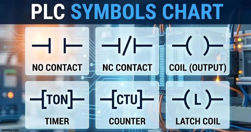
A PLC symbols chart provides a quick reference for identifying common symbols, instructions, and their purposes. It is useful for students, electrical technicians, automation engineers, and anyone learning to read PLC diagrams.
The following chart brings together commonly used ladder logic instructions and device abbreviations.
Common PLC Ladder Symbols Chart
| PLC symbol | Description | Purpose |
|—|—|—|
| —| |— | Normally Open Contact | Checks a true condition |
| —|/|— | Normally Closed Contact | Checks a false condition |
| —( )— | Output Coil | Controls a Boolean output |
| —(S)— | Set Coil | Sets a Boolean bit |
| —(R)— | Reset Coil | Resets a Boolean bit |
| TON | On-Delay Timer | Delays activation |
| TOF | Off-Delay Timer | Delays deactivation |
| RTO | Retentive Timer | Retains accumulated time |
| CTU | Count Up | Counts upward |
| CTD | Count Down | Counts downward |
| RES | Reset | Clears supported instruction data |
| ADD | Addition | Adds values |
| SUB | Subtraction | Subtracts values |
| MUL | Multiplication | Multiplies values |
| DIV | Division | Divides values |
| EQU | Equal | Compares two values |
| NEQ | Not Equal | Checks unequal values |
| GRT | Greater Than | Checks a greater value |
| LES | Less Than | Checks a smaller value |
| MOV | Move | Transfers data |
| AND | Logical AND | Performs an AND operation |
| OR | Logical OR | Performs an OR operation |
| XOR | Exclusive OR | Performs an exclusive OR operation |
| NOT | Logical NOT | Inverts a logical condition |
Common PLC Device Abbreviations Chart
| Abbreviation | Meaning |
| PLC | Programmable Logic Controller |
| DI | Digital Input |
| DO | Digital Output |
| AI | Analog Input |
| AO | Analog Output |
| PB | Push Button |
| LS | Limit Switch |
| PS | Pressure Switch |
| TS | Temperature Switch |
| FS | Flow Switch |
| M | Motor |
| K | Relay or Contactor |
| SOL | Solenoid |
| HMI | Human-Machine Interface |
| VFD | Variable Frequency Drive |
| E-STOP | Emergency Stop |
Important: The first chart contains programming instructions and ladder notation, while the second contains device abbreviations. They serve different purposes and should not be treated as one universal symbol standard.
PLC Ladder Diagram Symbols
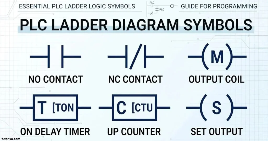
PLC ladder diagram symbols are graphical elements used to create ladder logic programs. Ladder logic is one of the most widely used PLC programming languages because its layout resembles traditional electrical relay control circuits.
A ladder diagram normally contains two vertical power rails and horizontal rungs. Each rung represents a logical operation that determines whether an output or instruction should execute.
The IEC 61131-3 standard defines Ladder Diagram (LD) as one of the graphical programming languages used for programmable controllers.
IEC+1
Main Ladder Diagram Symbols
Normally Open Contact
—| |—
Checks whether a Boolean variable is TRUE.
Normally Closed Contact
—|/|—
Checks whether a Boolean variable is FALSE.
Output Coil
—( )—
Writes the result of the rung logic to an output variable.
Parallel Branch
+—-| |—-+
| |
+—-| |—-+
Represents alternative logical paths. In this example, either true contact can complete the logical path.
Series Contacts
—| |——| |——( )—
Represents conditions that must all be true for the output to activate.
Example Of A Basic PLC Ladder Diagram
Consider a motor control circuit with a start button, a stop condition, and a motor output.
Start Stop Motor
|——| |———|/|———( )——|
In this simplified example:
- Start represents the motor start command.
- Stop represents the stop condition.
- Motor represents the output controlled by the rung.
- Both logical conditions must be true for the motor output to activate.
In a real motor control system, additional logic may be required for overload protection, emergency stopping, electrical interlocks, and safe operating conditions.
Series And Parallel Connections
Series connection (AND logic)
|—-| |—-| |—-( )—-|
Both conditions must be true before the output becomes true.
Parallel connection (OR logic)
|—-+—-| |—-+—-( )—-|
| |
+—-| |—-+
Either branch can provide a true logical path.
These two connection types are the foundation of many PLC ladder programs.
Ladder Logic PLC Symbols Chart
A ladder logic PLC symbols chart helps you identify programming elements without searching through an entire programming manual.
Below are commonly used ladder instructions, including their names and practical applications.
Contact And Coil Instructions
| Instruction | Meaning | Application |
| XIC | Examine If Closed | Checks whether a bit is true |
| XIO | Examine If Open | Checks whether a bit is false |
| OTE | Output Energize | Controls an output bit |
| OTL | Output Latch | Latches a bit on |
| OTU | Output Unlatch | Clears a latched bit |
| ONS | One-Shot | Produces a one-scan event under the specified conditions |
| OSR | One-Shot Rising | Detects a rising transition |
| OSF | One-Shot Falling | Detects a falling transition |
These instruction names are associated with Allen-Bradley Logix programming. Other PLC platforms may use different names or graphical representations.
Timer And Counter Instructions
| Instruction | Meaning | Application |
| TON | Timer On-Delay | Delays an operation |
| TOF | Timer Off-Delay | Delays turning off |
| RTO | Retentive Timer On | Retains accumulated time |
| CTU | Count Up | Counts incoming events |
| CTD | Count Down | Counts downward |
| RES | Reset | Resets supported instruction values |
Comparison Instructions
| Instruction | Meaning | Application |
| EQU | Equal | Compares two values |
| NEQ | Not Equal | Identifies different values |
| GRT | Greater Than | Checks whether a value is greater |
| GEQ | Greater Than or Equal | Checks a greater or equal value |
| LES | Less Than | Checks whether a value is smaller |
| LEQ | Less Than or Equal | Checks a smaller or equal value |
| LIM | Limit Test | Checks whether a value falls within a range |
Mathematical Instructions
| Instruction | Meaning |
| ADD | Addition |
| SUB | Subtraction |
| MUL | Multiplication |
| DIV | Division |
| MOD | Modulo operation |
| SQRT | Square root |
| ABS | Absolute value |
| NEG | Negation |
Data Handling Instructions
| Instruction | Meaning |
| MOV | Moves data |
| COP | Copies data |
| CLR | Clears data |
| FLL | Fills a data range |
| SWPB | Swaps bytes |
These instruction names and availability can vary by controller family and software version. Rockwell Automation provides an official instruction reference for its Logix Designer platform.
PLC Switch Symbols
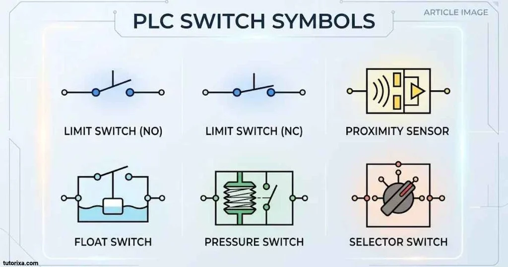
PLC switch symbols represent devices that detect changes in position, pressure, temperature, flow, or other operating conditions. These devices provide input signals that allow a PLC to monitor and control industrial equipment.
Switches are commonly used in manufacturing plants, conveyor systems, packaging machines, HVAC equipment, and other automated processes.
Here are some common PLC switch symbols and their applications.
1. Push Button Switch
A push button switch is a manually operated device used to send commands to a PLC.
Common applications include:
- Starting a machine.
- Stopping a motor.
- Resetting an alarm.
- Selecting an operating mode.
Its physical contact arrangement may be normally open or normally closed.
2. Limit Switch
A limit switch detects the position or movement of a mechanical component.
It is commonly installed on conveyor belts, machine doors, elevators, and automated equipment.
3. Pressure Switch
A pressure switch detects whether pressure reaches a selected threshold.
It can be used in:
- Air compressors.
- Hydraulic systems.
- Water pumps.
- Industrial pressure control systems.
4. Temperature Switch
A temperature switch changes its contact state when the temperature reaches a configured point.
It is useful in heating, cooling, and temperature protection systems.
5. Flow Switch
A flow switch detects the presence or absence of liquid or gas flow.
For example, it can send a signal to a PLC when water starts or stops flowing through a pipe.
6. Proximity Switch
A proximity switch detects an object without requiring direct mechanical contact.
Common types include:
- Inductive proximity sensors.
- Capacitive proximity sensors.
- Magnetic proximity sensors.
7. Photoelectric Switch
A photoelectric switch uses light to detect objects. It is frequently used in packaging lines, product counting systems, and conveyor automation.
PLC Switch Symbols Quick Reference
| Switch type | Common abbreviation | Main purpose |
| Push Button | PB | Manual control |
| Limit Switch | LS | Position detection |
| Pressure Switch | PS | Pressure detection |
| Temperature Switch | TS | Temperature detection |
| Flow Switch | FS | Flow detection |
| Proximity Switch | PS or PROX | Object detection |
| Photoelectric Sensor | PE | Optical detection |
| Selector Switch | SS | Mode selection |
| Float Switch | FS | Liquid level detection |
The same abbreviations can represent different devices in different industries. Always check the project legend and wiring diagram.
PLC Symbols In P&ID
P&ID stands for Piping and Instrumentation Diagram. It is an engineering drawing that shows the equipment, piping, valves, instruments, and control relationships within an industrial process.
PLC-related information in a P&ID helps engineers understand how instruments communicate with the control system.
Unlike ladder diagrams, P&ID drawings focus on the physical process and its instrumentation rather than the internal programming logic of the PLC.
The ANSI/ISA-5.1 standard provides a widely used framework for instrumentation and control symbols and identification. Its 2024 edition is titled Instrumentation and Control – Symbols and Identification.
Common P&ID Instrument Symbols And Tags
Here are common instrument identification abbreviations used in P&ID drawings.
| Tag | Meaning | Function |
| PT | Pressure Transmitter | Measures pressure |
| PI | Pressure Indicator | Displays pressure |
| PC | Pressure Controller | Controls pressure |
| TT | Temperature Transmitter | Measures temperature |
| TI | Temperature Indicator | Displays temperature |
| TC | Temperature Controller | Controls temperature |
| FT | Flow Transmitter | Measures flow |
| FI | Flow Indicator | Displays flow |
| FC | Flow Controller | Controls flow |
| LT | Level Transmitter | Measures liquid level |
| LI | Level Indicator | Displays liquid level |
| LC | Level Controller | Controls liquid level |
These tags are based on common instrumentation identification conventions. Their exact interpretation depends on the applicable drawing standard and project documentation.
Common PLC-Related P&ID Elements
| Element | Description |
| PLC | Programmable logic controller |
| DCS | Distributed control system |
| HMI | Human-machine interface |
| I/O | Input and output points |
| DI | Digital input |
| DO | Digital output |
| AI | Analog input |
| AO | Analog output |
| Control Valve | Regulates process flow |
| Transmitter | Sends a measured process signal |
Difference Between PLC And P&ID Symbols
| PLC ladder diagram | P&ID diagram |
| Shows control logic | Shows process equipment and instrumentation |
| Uses contacts and coils | Uses instrument bubbles and process symbols |
| Represents logical conditions | Represents measurement and control functions |
| Used for PLC programming | Used for process design and documentation |
| Shows rung-by-rung operations | Shows process relationships |
For example, a temperature transmitter may appear as TT on a P&ID. The corresponding PLC program may use a numerical input tag to read its measurement and control a heater.
The two drawings describe different parts of the same automation system.
HVAC Ladder Diagram Symbols
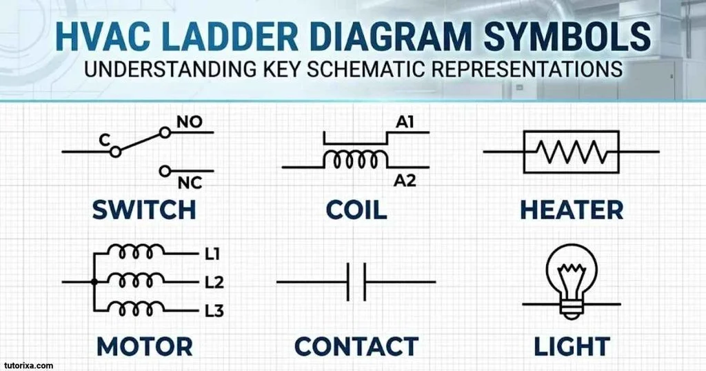
HVAC stands for Heating, Ventilation, and Air Conditioning. HVAC ladder diagrams show the electrical control logic used in heating and cooling equipment.
These diagrams help technicians understand how thermostats, compressors, fans, relays, contactors, and safety switches work together.
PLC-based HVAC systems use ladder logic to control equipment according to temperature, pressure, airflow, and operating conditions.
Common HVAC Symbols
| Symbol or abbreviation | Name | Function |
| TH | Thermostat | Detects or controls temperature |
| COMP | Compressor | Compresses refrigerant |
| FAN | Fan | Moves air |
| BLWR | Blower | Circulates air |
| M | Motor | Drives mechanical equipment |
| K | Relay or Contactor | Switches electrical circuits |
| SOL | Solenoid | Operates a valve |
| PS | Pressure Switch | Monitors pressure |
| FS | Flow Switch | Monitors airflow or fluid flow |
| TS | Temperature Switch | Monitors temperature |
| OL | Overload | Provides motor overload protection |
| HP | High-Pressure Switch | Monitors excessive pressure |
| LP | Low-Pressure Switch | Monitors low pressure |
The abbreviations above are common drawing labels, not a universal symbol set.
Common HVAC Control Components
Thermostat: Monitors the room temperature and provides a heating or cooling demand.
Compressor: Circulates refrigerant through the refrigeration system.
Blower motor: Moves conditioned air through the ductwork.
Contactor: Switches power to equipment such as compressors and motors.
Pressure switch: Monitors system pressure and can provide a protective control input.
Temperature sensor: Sends temperature information to the controller.
Example Of An HVAC Ladder Logic Program
A simplified PLC-controlled fan circuit might look like this:
Fan Demand Safety OK Fan Output
|——-| |————-| |————-( )——|
The fan output becomes active when the fan demand is true and the safety condition is satisfied.
A more advanced HVAC control program may include:
- Temperature-based fan control.
- Compressor start and stop delays.
- Heating and cooling mode selection.
- Filter alarm monitoring.
- Fan failure detection.
- Pressure and temperature protection.
Actual HVAC electrical wiring diagrams may use different symbols depending on the equipment manufacturer and applicable electrical drawing standards.
Allen Bradley PLC Symbols
Allen-Bradley PLCs are manufactured by Rockwell Automation. They are widely used in industrial automation applications, including manufacturing, packaging, material handling, and process control.
Allen-Bradley PLC programming commonly uses ladder logic through Studio 5000 Logix Designer and related software.
Its ladder logic instructions include specific names that may look different from the graphical symbols used in other PLC platforms.
Common Allen-Bradley PLC Instructions
| Instruction | Full name | Function |
| XIC | Examine If Closed | Tests whether a bit is true |
| XIO | Examine If Open | Tests whether a bit is false |
| OTE | Output Energize | Controls an output bit |
| OTL | Output Latch | Latches a bit on |
| OTU | Output Unlatch | Unlatches a bit |
| ONS | One-Shot | Creates a one-scan event |
| TON | Timer On-Delay | Delays activation |
| TOF | Timer Off-Delay | Delays deactivation |
| RTO | Retentive Timer On | Retains accumulated time |
| CTU | Count Up | Increases a counter |
| CTD | Count Down | Decreases a counter |
| RES | Reset | Resets supported instruction data |
Allen-Bradley Ladder Logic Examples
Examine If Closed (XIC)
—| |—
This instruction evaluates as true when the referenced Boolean tag is true.
Examine If Open (XIO)
—|/|—
This instruction evaluates as true when the referenced Boolean tag is false.
Output Energize (OTE)
—( )—
This instruction writes the rung result to its associated output tag.
Output Latch (OTL)
—(L)—
This instruction latches a Boolean tag when its rung conditions are satisfied.
Output Unlatch (OTU)
—(U)—
This instruction clears a previously latched Boolean tag when its rung conditions are satisfied.
The exact graphical appearance of instructions can vary with the programming environment. Rockwell Automation’s Studio 5000 documentation provides the official instruction reference for supported Logix controllers.
Rockwell Automation+1
Siemens PLC Symbols
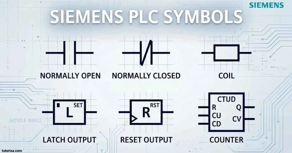
Siemens PLCs are commonly programmed using TIA Portal (Totally Integrated Automation Portal). Siemens controllers are used in manufacturing, industrial machinery, process control, and building automation.
Siemens supports several PLC programming languages, including Ladder Diagram (LAD), Function Block Diagram (FBD), and Structured Control Language (SCL).
Its ladder logic uses familiar contact and coil elements, although the programming interface and available instructions can differ from other manufacturers.
Common Siemens PLC Ladder Symbols
| Symbol or notation | Name | Function |
|—|—|—|
| —| |— | Normally Open Contact | Checks a true condition |
| —|/|— | Normally Closed Contact | Checks a false condition |
| —( )— | Output Coil | Writes a Boolean output |
| TON | On-Delay Timer | Delays an operation |
| TOF | Off-Delay Timer | Delays an operation turning off |
| TP | Pulse Timer | Generates a timed pulse |
| CTU | Count Up | Increases a counter |
| CTD | Count Down | Decreases a counter |
| MOVE | Move | Transfers data |
| ADD | Add | Adds numerical values |
| SUB | Subtract | Subtracts numerical values |
Siemens PLC Input And Output Address Examples
Siemens PLC programs often use address notation to identify physical input and output locations.
| Address | Meaning |
| %I0.0 | Digital input, byte 0, bit 0 |
| %I0.1 | Digital input, byte 0, bit 1 |
| %I1.0 | Digital input, byte 1, bit 0 |
| %Q0.0 | Digital output, byte 0, bit 0 |
| %Q0.1 | Digital output, byte 0, bit 1 |
| %Q1.0 | Digital output, byte 1, bit 0 |
| %M0.0 | Memory bit, byte 0, bit 0 |
These are examples of Siemens absolute addressing. Actual addresses depend on the hardware configuration, project settings, and symbolic tag assignments.
Siemens PLC Ladder Logic Example
Consider a basic motor control program:
Start Stop Motor
|—-| |———|/|———( )—-|
In a Siemens LAD program, the contacts and output coil are assigned PLC tags or addresses.
For example:
- Start: %I0.0
- Stop: %I0.1
- Motor: %Q0.0
This example illustrates the basic logic relationship. A practical motor circuit should include appropriate protective devices, interlocks, and safety functions.
AutoCAD PLC Symbols
AutoCAD is widely used for creating electrical drawings, control panel layouts, wiring diagrams, and industrial automation documentation.
AutoCAD Electrical provides specialized tools and symbol libraries for electrical control design. Engineers can use these libraries to insert PLC-related components, create wiring diagrams, and document input and output connections.
Common AutoCAD PLC Symbols
| Symbol or component | Description |
| PLC Input Module | Represents digital or analog input connections |
| PLC Output Module | Represents digital or analog output connections |
| Normally Open Contact | Represents an open contact condition |
| Normally Closed Contact | Represents a closed contact condition |
| Relay Coil | Represents a relay control coil |
| Contactor | Represents a switching device |
| Motor | Represents an electric motor |
| Push Button | Represents a manual control device |
| Limit Switch | Represents a position-detection device |
| Sensor | Represents an input detection device |
| Terminal Block | Represents an electrical connection point |
| Ground | Represents an electrical grounding connection |
AutoCAD Electrical PLC Module Symbols
PLC modules are commonly represented according to their function and the drawing standard being used.
Digital Input Module (DI)
Receives ON/OFF signals from devices such as push buttons, limit switches, and proximity sensors.
Digital Output Module (DO)
Sends ON/OFF control signals to devices such as relays, contactors, and indicator lamps.
Analog Input Module (AI)
Receives continuously varying signals from devices such as pressure, temperature, and flow transmitters.
Analog Output Module (AO)
Sends variable control signals to devices such as control valves and variable frequency drives.
Where To Find PLC Symbols In AutoCAD Electrical
You can access PLC symbols and related components through the electrical symbol libraries and PLC tools.
A typical workflow includes:
- Open your AutoCAD Electrical project.
- Select the schematic tools.
- Locate the PLC or I/O module insertion tools.
- Choose the required PLC module or component.
- Insert it into the drawing.
- Assign the correct input and output information.
- Add wire connections and component descriptions.
- Review the drawing and update its project documentation.
The exact menu names and available libraries depend on the AutoCAD Electrical version and installed symbol standards.
AutoCAD PLC Symbol Libraries
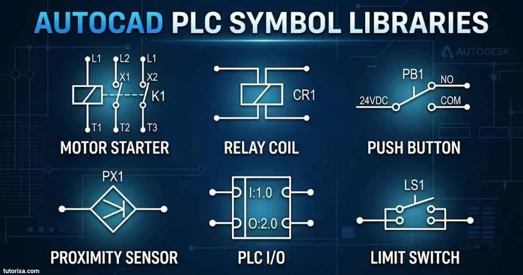
When working with AutoCAD Electrical, you may encounter different symbol library conventions.
- IEC: Commonly used for international electrical documentation.
- JIC: A historical drawing convention associated with industrial control diagrams in North America.
- NFPA: An important family of electrical and industrial control standards used in North America.
Choose the symbol library that matches your project’s requirements. Do not mix different symbol conventions without clearly documenting the differences.
Frequently Asked Questions About PLC Symbols
1. What Are The Most Common PLC Symbols?
The most common PLC symbols include normally open contacts, normally closed contacts, output coils, set and reset coils, timers, counters, and comparison instructions. Push buttons, sensors, relays, and motors are also frequently represented in PLC electrical drawings.
2. What Is The Difference Between NO And NC Symbols In PLC?
A normally open contact instruction (—| |—) is true when its assigned Boolean variable is TRUE. A normally closed contact instruction (—|/|—) is true when that variable is FALSE. These logical instructions should not be confused with the physical wiring arrangement of a switch.
3. What Is The Standard For PLC Ladder Diagram Symbols?
IEC 61131-3 defines programming languages for programmable controllers, including Ladder Diagram (LD). However, individual PLC manufacturers may use different instruction names, features, and graphical conventions.
4. Are Allen-Bradley And Siemens PLC Symbols The Same?
They share many basic ladder logic concepts, such as normally open contacts, normally closed contacts, and output coils. However, their instruction names, addressing methods, software interfaces, and programming features can differ.
5. Where Can I Download PLC Symbols And Meanings PDF?
You can find PLC symbol references in manufacturer documentation, electrical engineering textbooks, and automation training resources. Rockwell Automation and Siemens provide official PLC programming documentation. For P&ID instrumentation symbols, consult the applicable ISA-5.1 standard.
Conclusion
PLC symbols make industrial automation drawings and programs easier to understand. They help engineers and technicians identify inputs, outputs, switches, timers, counters, and other control elements. Understanding their meanings is a useful first step toward learning PLC programming and reading electrical diagrams.
Different applications use different symbol conventions. Ladder logic symbols describe programming instructions, P&ID symbols represent process instruments, and AutoCAD libraries provide graphical components for electrical documentation. Allen-Bradley and Siemens also have their own instruction names and programming environments.
Start by learning the basic contact and coil symbols, then move on to timers, counters, switches, and manufacturer-specific instructions. Always check the relevant drawing legend and PLC documentation before using a symbol in an actual project. This will help you read diagrams more accurately and work confidently with industrial control systems.

I’m Rowan Whitaker, a British writer fascinated by the symbols surrounding us every day. I explore their meanings, origins, cultural significance, and changing interpretations. From ancient marks to modern signs, I enjoy making symbolism easier to understand. My writing helps curious readers discover the hidden messages behind familiar shapes, images, and signs.
Books:
- The Meaning Behind Symbols
- A Modern Guide to Symbolism
 Freddie Beaumont
 Ellis Montgomery