
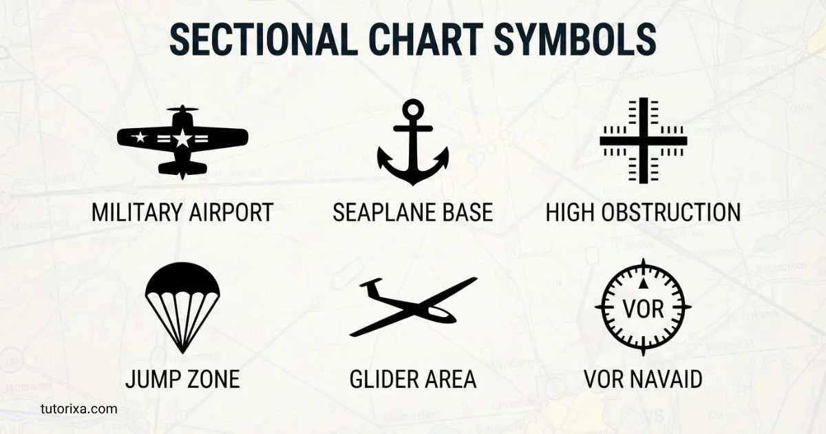
When I first look at a sectional chart, the many lines, shapes, and symbols can feel confusing. You may wonder what each mark means and how pilots quickly understand all that information.
I want to make Sectional Chart Symbols much easier for you. In this guide, I’ll break down the important symbols in simple language so you can understand what you’re seeing without feeling overwhelmed.
Whether you’re a beginner, student pilot, aviation enthusiast, or simply curious about aeronautical charts, you’ll find practical explanations here. By the end, you’ll have a clearer idea of how these symbols communicate essential information.
Quick Meaning of Sectional Chart Symbols
Sectional chart symbols are standardized markings used on VFR aeronautical charts to represent aviation and geographic information. They identify airports, airspace boundaries, navigation aids, obstacles, terrain, water, roads, railroads, landmarks, and special-use areas. Their colors, shapes, line styles, letters, and numbers work together to communicate information efficiently to pilots.
Sectional Chart Symbols Overview
| Field | Information |
| Symbol Name | Sectional chart symbols |
| Primary Meaning | Visual representation of aeronautical, topographic, and operational information |
| Category | Aviation cartography / VFR navigation |
| Primary System | FAA VFR sectional chart symbology |
| Country Focus | United States |
| Main Users | VFR pilots, student pilots, aviation students, drone operators, and other chart users |
| Chart Scale | 1:500,000 |
| Scale Equivalent | Approximately 1 inch = 6.86 nautical miles |
| Common Information | Airports, airspace, terrain, obstacles, NAVAIDs, landmarks, roads, railroads, waterways |
| Official Reference | FAA Aeronautical Chart User’s Guide |
| Chart Revision | Generally every 56 days |
| Unicode | Not applicable as a single character |
| Emoji Equivalent | No official emoji equivalent |
| Related Symbols | Airport symbols, airspace boundaries, VOR symbols, obstruction symbols, terrain markings, navigation symbols |
FAA describes sectional aeronautical charts as the primary navigational reference for the VFR pilot community. They use a 1:500,000 scale and combine aeronautical information with topographic and cultural features.
What Do Sectional Chart Symbols Mean?
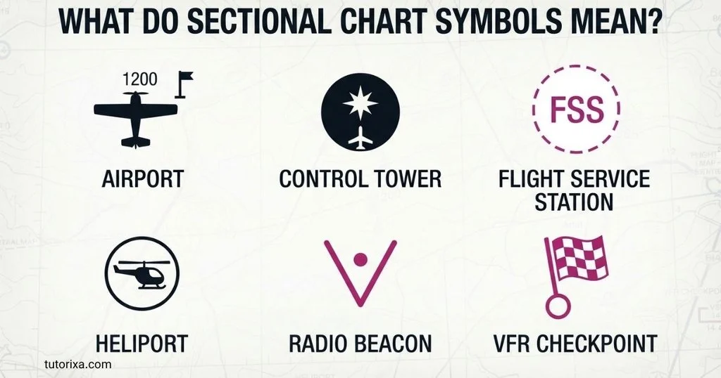
Sectional chart symbols mean different things depending on their shape, color, line pattern, label, and surrounding information. There is no single “sectional chart symbol.” Instead, the term refers to an extensive system of symbols used together.
For example, an airport symbol tells you that an airport exists, while its color and accompanying information provide additional clues about the facility. An airspace boundary tells you that the operating rules change across that line. A tower or obstruction symbol alerts the chart reader to a vertical obstacle.
The most important categories include:
- Airport symbols — show airports and related facilities.
- Airspace symbols — identify boundaries and classes of airspace.
- Navigation symbols — show radio navigation aids and related information.
- Obstacle symbols — identify towers, antennas, and other vertical structures.
- Terrain symbols — communicate elevation, relief, contours, and maximum elevation figures.
- Hydrographic symbols — identify oceans, lakes, rivers, and other water features.
- Cultural symbols — show cities, roads, railroads, landmarks, and other recognizable features.
- Special-use airspace symbols — identify areas with special operating considerations or restrictions.
This system exists because a sectional chart must communicate information over a large geographic area without becoming an unreadable page of text. FAA sectional charts combine aeronautical, topographic, and cultural information specifically for visual navigation.
History and Origin of Sectional Chart Symbols
Sectional chart symbols developed from the broader history of aeronautical cartography. Aviation maps needed a consistent visual language because pilots had to recognize airports, terrain, navigation aids, hazards, and geographic landmarks from a map.
The modern FAA sectional chart system is part of the United States’ standardized aeronautical charting system. The FAA’s Aeronautical Information Services develops and maintains U.S. visual and instrument aeronautical chart products, while the Aeronautical Chart User’s Guide documents the symbols used on those products.
A sectional chart is not simply a road map with airports added. It combines several forms of cartographic information:
- Aeronautical information — airports, airspace, navigation aids, and obstacles.
- Topographic information — elevation, terrain, drainage, and relief.
- Cultural information — cities, roads, railroads, and recognizable landmarks.
The FAA currently describes sectional charts as 1:500,000-scale charts designed for visual navigation by slow- to medium-speed aircraft. They are generally revised on a 56-day cycle.
The symbols have therefore evolved alongside aviation itself. As airports, airspace classifications, electronic navigation, communications systems, and other aviation requirements changed, charting standards also developed.
How Sectional Chart Symbols Are Organized
Sectional chart symbols are easier to understand when you treat the chart as a layered information system.
1. Aeronautical Layer
This includes airports, airspace, navigation aids, routes, and aviation facilities.
2. Terrain Layer
This includes elevation information, contour lines, shaded relief, mountains, valleys, and maximum elevation information.
3. Obstacle Layer
This identifies objects that can be significant to aircraft, such as towers and other tall structures.
4. Geographic Layer
This includes water bodies, coastlines, islands, cities, roads, railroads, and other geographic features.
5. Regulatory or Special-Use Layer
This communicates areas such as restricted or special-use airspace and other operational considerations.
Understanding these layers is more useful than memorizing isolated shapes because a single location on the chart may contain several symbols simultaneously.
Common Sectional Chart Airport Symbols
Airport symbols are among the most important sectional chart symbols because they identify places where aircraft may operate.
The chart can communicate information about an airport through its symbol, color, runway depiction, surrounding markings, and airport data.
Common information associated with an airport includes:
- Airport name or identifier
- Runway configuration
- Field elevation
- Runway characteristics
- Communication frequencies
- Airport operating information
- Whether the airport is towered or non-towered
- Whether special conditions apply
A particularly important point is that the airport symbol alone is not always enough. The surrounding airport data and current supporting publications can provide operational information that cannot be fully represented graphically.
The FAA’s charting guidance includes airport, runway, communications, and related data in its VFR chart symbology.
Sectional Chart Airspace Symbols
Airspace symbols show where different airspace boundaries and operating requirements occur.
Class B Airspace
Class B airspace is commonly represented by solid blue boundary lines on U.S. VFR charts. Its boundaries may form multiple layers around major airports.
Altitude information is essential because the boundaries can have different vertical limits at different locations.
Class C Airspace
Class C airspace is commonly depicted with solid magenta boundaries, generally forming rings or shelves around qualifying airports.
Again, the chart’s altitude information is just as important as the boundary itself.
Class D Airspace
Class D surface areas are commonly shown with a dashed blue boundary.
The symbol indicates the lateral boundary, while the accompanying information helps establish the relevant vertical limits.
Class E Airspace
Class E airspace can be represented in several ways depending on the type and location of the airspace. This is one reason users should not attempt to interpret an unfamiliar line from color alone.
Special-Use Airspace
Sectional charts also identify areas such as restricted areas, prohibited areas, warning areas, military operations areas, and other special-use or special-activity areas.
The exact symbol and associated information should always be checked against the current FAA chart legend.
Navigation Aid Symbols
Navigation aids, commonly called NAVAIDs, help aircraft determine position, direction, or navigation information.
Common examples include:
- VOR
- VOR/DME
- VORTAC
- Other radio navigation facilities
A VOR is generally represented by a distinctive compass-like or circular navigation symbol with identifying information.
The surrounding label may provide:
- Facility identifier
- Frequency
- Name
- Associated information
The important lesson is that the symbol identifies the facility, while the accompanying data tells you how it is identified and what information is associated with it.
Sectional charts specifically include visual and radio aids to navigation as part of their aeronautical information.
Obstruction Symbols
Obstruction symbols identify objects that may be significant to aviation because of their height or location.
Examples can include:
- Towers
- Radio towers
- Television towers
- Antennas
- Other tall structures
The FAA’s current chart guide explains that obstruction information is incorporated into sectional chart symbology. It also notes that some landmark and obstruction symbols may be enlarged on the chart so they remain readable at chart scale.
A tower symbol may be accompanied by elevation or height information. Those numbers should not be interpreted casually because aviation charts distinguish between different types of elevation measurements.
This is an excellent example of why a symbol should be read together with its label rather than viewed as an isolated picture.
Terrain and Elevation Symbols
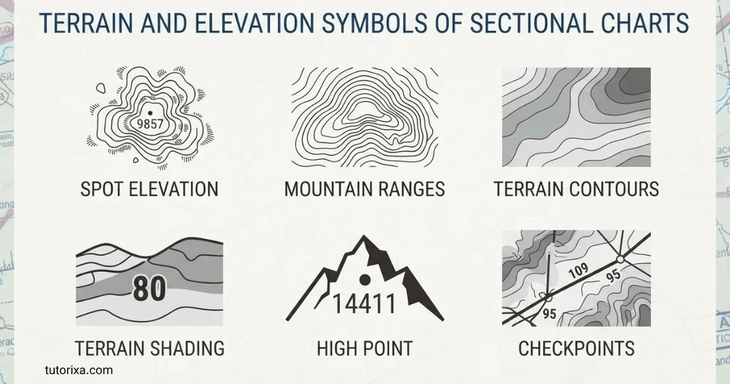
Terrain symbols communicate the shape and height of the land.
Important features include:
- Contour lines
- Elevation information
- Shaded relief
- Maximum Elevation Figures (MEFs)
- Mountainous terrain
- Significant geographic features
Contour lines help show changes in elevation. Closely spaced contours generally indicate a steeper change in terrain, while widely spaced contours indicate a more gradual change.
Maximum Elevation Figures provide an important elevation reference for a quadrangle on the chart. They account for terrain and certain obstructions within the area.
Terrain information is particularly valuable during visual navigation because a pilot needs to understand not only where an aircraft is horizontally but also what significant terrain exists below and around the route.
Water and Hydrographic Symbols
Water features are also part of sectional chart symbology.
The FAA guide describes different treatments for open water and inland water. Open water includes coastal features such as oceans, seas, bays, gulfs, sounds, and large estuaries, while other bodies of water are depicted as inland water.
Water features can serve as:
- Navigation references
- Visual checkpoints
- Geographic boundaries
- Orientation landmarks
Their appearance is therefore not merely decorative. They contribute to visual navigation and geographic awareness.
Roads, Railroads, Cities, and Landmarks
Sectional charts include selected cultural features because recognizable objects on the ground can help pilots maintain situational awareness.
These may include:
- Cities
- Towns
- Highways
- Roads
- Railroads
- Stadiums
- Refineries
- Pumping stations
- Other distinctive landmarks
The FAA guide explains that certain landmarks are represented with small symbols and descriptive labels.
These features demonstrate an important principle of sectional chart design: not every geographic feature needs to be shown. The chart selects information that is useful for aviation navigation while maintaining readability.
Symbolism and Interpretation of Sectional Chart Symbols
Unlike religious or artistic symbols, sectional chart symbols generally do not have symbolic meanings in the cultural or psychological sense.
Their meaning is technical and standardized.
For example:
- A blue boundary does not represent a cultural idea of blue.
- A tower icon is not symbolic artwork.
- A contour line is not metaphorical.
- An airport symbol does not represent aviation in a philosophical sense.
Instead, each visual element functions as a compact information code.
This distinction is important because people sometimes search for “sectional chart symbolism” as though these markings were ordinary cultural symbols. Their meanings come primarily from cartographic standards, aviation regulations, and charting conventions.
Cultural Significance
Sectional chart symbols have limited cultural symbolism, but they have significant practical importance within aviation culture.
Pilots, flight instructors, aviation students, dispatchers, and other aviation professionals use a shared visual vocabulary. A standardized chart symbol allows someone familiar with the system to understand information without needing a long textual explanation.
This is similar to the way road signs create a shared language for drivers.
The symbols also reflect the geography and infrastructure of the United States. Cities, railways, highways, rivers, airports, military facilities, and industrial landmarks all become part of a visual representation of the landscape.
Scientific and Technical Meaning
The technical meaning of sectional chart symbols is their most important dimension.
They are used in:
- Aviation navigation
- Airspace planning
- Terrain awareness
- Obstacle identification
- Geographic orientation
- Flight training
- Aviation chart interpretation
- Unmanned aircraft education
A sectional chart uses a standardized scale of 1:500,000, equivalent to approximately 6.86 nautical miles per inch.
That scale creates an important design challenge. A real airport runway, tower, road, or small landmark may be too small to display at its true physical size. Consequently, some chart symbols are intentionally enlarged or stylized so users can identify them.
The FAA specifically notes that the scale of some items may be increased to make them easier to read.
Where Sectional Chart Symbols Are Used
Sectional chart symbols are primarily encountered on VFR sectional aeronautical charts, but related symbology can appear across other FAA visual chart products.
You may encounter them in:
- Printed sectional charts
- Digital sectional charts
- Electronic flight bag displays
- Aviation training materials
- Pilot ground-school courses
- Flight planning
- FAA knowledge-test preparation
- Part 107 education
- Aviation research
- Aeronautical chart references
The FAA states that its Aeronautical Chart User’s Guide contains listings of charting symbols and their meanings for its aeronautical products.
Common Variations in Sectional Chart Symbols
Sectional chart symbols vary according to what they represent and the chart on which they appear.
Variations can involve:
Color
Different colors help separate categories such as airports, airspace, terrain, and geographic features.
Line Style
Solid, dashed, and other line patterns can communicate different types of boundaries.
Shape
Circles, rings, points, runway shapes, and specialized icons distinguish different features.
Labels
Letters and numbers provide information that a simple graphic cannot communicate.
Scale
A symbol may be enlarged or stylized because an exact physical representation would be too small to read.
Chart Type
Some visual chart products share related symbology while using different scales or emphasizing different information. The FAA notes that the same general symbology can be used across several VFR products, although symbol scale can differ.
Common Misconceptions About Sectional Chart Symbols
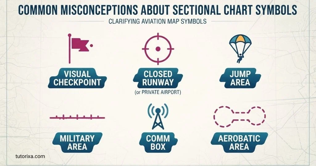
Misconception 1: Every symbol can be understood from its picture
Not necessarily. Many symbols depend on color, line style, nearby labels, or altitude information. The legend should be consulted whenever a symbol is unfamiliar.
Misconception 2: A sectional chart is just an aviation road map
A sectional chart is much more specialized. It combines aeronautical information with topography, terrain, obstacles, waterways, and selected cultural landmarks.
Misconception 3: All lines represent roads
Many lines represent airspace boundaries, geographic features, routes, or other chart information. Line style and color matter.
Misconception 4: The chart never changes
Sectional charts are updated regularly. FAA sectional charts generally follow a 56-day revision cycle.
Misconception 5: Memorizing symbols is enough
Understanding the relationship between the symbol, label, altitude, color, and chart legend is more reliable than memorizing isolated icons.
Misconception 6: Every geographic feature is shown
A sectional chart is selective. It cannot display every road, building, tree, or geographic detail at its scale.
10 Interesting Facts About Sectional Chart Symbols
- A sectional chart is a layered map.
Aeronautical, geographic, topographic, and obstacle information can appear in the same small area. - The standard scale is 1:500,000.
One inch represents approximately 6.86 nautical miles, allowing a single chart to cover a substantial geographic region. - Symbols are not always drawn to physical scale.
Some features are enlarged so users can identify them clearly. - Colors carry information.
Color is part of the chart’s information system, not merely a visual design choice. - Line patterns matter.
Two boundaries that look similar can have different meanings depending on whether they are solid, dashed, blue, magenta, or another standardized style. - Terrain and aviation information coexist.
A sectional chart can tell you about an airport and the surrounding terrain on the same map. - Sectionals include cultural landmarks.
Cities, railroads, roads, stadiums, and industrial landmarks can provide useful visual references. - The symbols have an official reference system.
The FAA’s Aeronautical Chart User’s Guide documents charting symbols and their meanings. - Chart freshness matters.
FAA sectional charts are generally revised every 56 days, reflecting the changing nature of aviation information. - A symbol may need accompanying text.
The graphic alone may identify a feature, while nearby numbers, letters, or abbreviations provide the information needed to interpret it correctly.
Related Symbols
Several symbol systems are closely connected to sectional chart symbols:
- Airport symbols — identify airports, runways, and airport characteristics.
- Airspace symbols — show boundaries and classifications.
- VOR symbols — identify radio navigation facilities.
- Obstacle symbols — identify towers and other vertical structures.
- Terrain symbols — communicate elevation and relief.
- Hydrographic symbols — represent water features.
- Topographic symbols — show terrain and geographic characteristics.
- Special-use airspace symbols — identify areas with specific operational considerations.
- Railroad and highway symbols — provide visual geographic references.
- Landmark symbols — identify distinctive objects that may be recognizable from the air.
The major difference between these groups is the type of information they encode. An airport symbol answers “Where is the airport?” while an airspace boundary answers “Where does this airspace apply?” A terrain marking answers “What is the elevation or shape of the land?” Each symbol contributes another piece of the navigation picture.
Frequently Asked Questions
What are sectional chart symbols?
Sectional chart symbols are standardized visual markings used on U.S. VFR aeronautical charts. They represent airports, airspace, navigation aids, obstacles, terrain, water, roads, railroads, cities, landmarks, and other information relevant to visual flight. Their meaning depends on standardized colors, shapes, lines, numbers, letters, and labels.
What is the purpose of a sectional chart?
A sectional chart provides geographic and aeronautical information needed for visual navigation. It shows airports, controlled and special-use airspace, navigation aids, obstacles, terrain, landmarks, roads, railroads, and waterways. FAA sectional charts are designed specifically for visual navigation by slow- to medium-speed aircraft.
What do the colors mean on a sectional chart?
Colors distinguish different categories of information. For example, blue and magenta are important in depicting certain airspace and airport information, while blue is also used for water features. However, color should never be interpreted independently from the symbol, line style, label, and current chart legend.
What do airport symbols mean on a sectional chart?
Airport symbols identify airports and provide a visual representation of the facility. Additional information around the symbol can communicate airport identification, elevation, runway characteristics, communication frequencies, and other operational details. The precise meaning depends on the airport symbol and its accompanying chart data.
What do blue lines mean on a sectional chart?
A blue line can have different meanings depending on its form and location. For example, solid blue boundaries are commonly associated with Class B airspace, while dashed blue boundaries are commonly associated with Class D surface areas. Always interpret the line using the current sectional chart legend and accompanying altitude information.
What do magenta lines mean on a sectional chart?
Magenta is used for several types of information on VFR charts. A common example is the solid magenta boundary associated with Class C airspace. Magenta may also appear in other charting contexts, so the exact line style and surrounding information should be checked before interpreting a particular marking.
Are sectional chart symbols the same everywhere?
They are standardized within the applicable charting system, but symbols can vary between different chart products and countries. FAA sectional charts follow U.S. aeronautical charting standards. Other countries may use different symbols, colors, abbreviations, and conventions. Even within U.S. products, scale and presentation can vary between chart types.
How often are sectional charts updated?
FAA sectional aeronautical charts are generally updated every 56 days. This regular cycle helps keep information such as airports, airspace, navigation aids, and obstacles current. The FAA provides current visual chart products and charting guidance through its Aeronautical Information Services.
Where can I find the official meaning of a sectional chart symbol?
The FAA’s Aeronautical Chart User’s Guide is the authoritative reference for FAA chart symbols. The FAA specifically directs users to this guide for aeronautical chart symbols and their meanings. When interpreting a chart for actual aviation purposes, use the current official chart and applicable FAA publications rather than relying on an old diagram or memory alone.
Key Takeaways
- Sectional chart symbols form a standardized visual language for VFR aviation charts.
- They identify airports, airspace, NAVAIDs, obstacles, terrain, water, roads, railroads, and landmarks.
- Their meanings depend on color, shape, line style, labels, and numbers.
- FAA sectional charts use a 1:500,000 scale.
- Sectional charts combine aeronautical, topographic, and cultural information.
- Some symbols are intentionally enlarged or stylized for readability.
- Airport and airspace symbols are especially important for aviation students.
- Terrain and obstruction symbols provide important geographic and vertical information.
- The FAA’s Aeronautical Chart User’s Guide is the key reference for official symbol meanings.
- Sectional charts are generally revised on a 56-day cycle.
- An unfamiliar symbol should be checked against the current chart legend, not guessed.
- Sectional chart symbols are technical cartographic conventions rather than cultural or religious symbols.
Conclusion
Sectional chart symbols are the compact visual language that makes a complex aviation map understandable. A single sectional chart can communicate airports, airspace boundaries, navigation aids, terrain, obstacles, waterways, roads, cities, and recognizable landmarks without filling the map with lengthy descriptions.
The most effective way to understand them is to look at the entire information system rather than memorizing individual icons. Color tells you one thing, line style another, the symbol provides another clue, and nearby numbers or letters complete the meaning. Together, these elements turn a detailed geographic map into a practical VFR navigation reference.
Because aviation information changes, the current chart and official FAA charting guidance should always take priority over older examples. The FAA identifies its Aeronautical Chart User’s Guide as the reference for chart symbols, while its current sectional chart system continues to provide standardized information for visual navigation.

I’m Rowan Whitaker, a British writer fascinated by the symbols surrounding us every day. I explore their meanings, origins, cultural significance, and changing interpretations. From ancient marks to modern signs, I enjoy making symbolism easier to understand. My writing helps curious readers discover the hidden messages behind familiar shapes, images, and signs.
Books:
- The Meaning Behind Symbols
- A Modern Guide to Symbolism
 Ellis Montgomery
 Freddie Beaumont