
Understanding automotive wiring diagrams can feel confusing when you first encounter unfamiliar lines, shapes, and electrical symbols. I know how frustrating it can be to look at a diagram and wonder what each symbol means or how the components connect.
Automotive wiring diagram symbols help you understand how electrical components connect and work together in a vehicle. Once you learn to recognize these symbols, you can read wiring diagrams with greater confidence and identify important circuits more easily.
In this guide, I’ll explain the most common automotive wiring diagram symbols, what they represent, and how you can recognize them in real diagrams. Whether you’re a beginner, a student, or a DIY car enthusiast, you’ll find practical explanations to help you understand automotive electrical systems.
Quick Meaning of Automotive Wiring Diagram Symbols
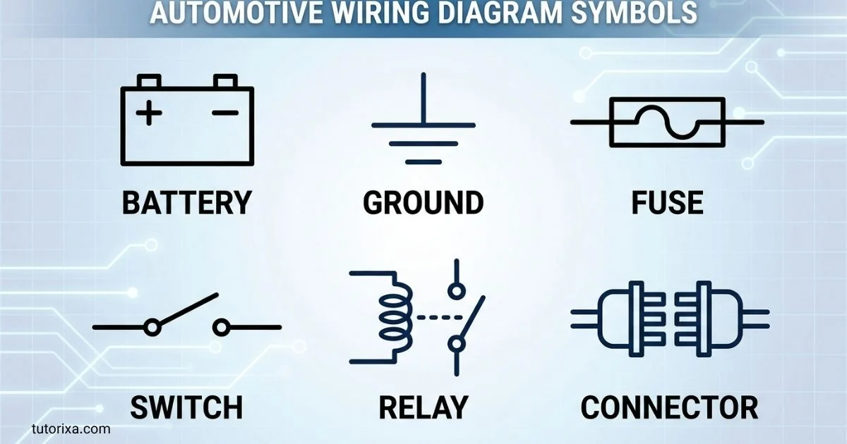
Automotive wiring diagram symbols are standardized or manufacturer-specific graphical representations of electrical components and connections in a vehicle. They show how batteries, fuses, relays, switches, sensors, lights, motors, and control modules interact within a circuit. Technicians use these symbols to trace electrical paths, understand circuit operation, and diagnose electrical faults.
Automotive Wiring Diagram Symbols: Overview Table
The following table explains common automotive electrical symbols and their general functions. Actual shapes and drawing conventions can vary by manufacturer and diagram type.
| Symbol or Label | Component Name | Primary Function | Common Application |
| Battery plates or battery label | Battery | Supplies electrical energy | Starting and vehicle power |
| Fuse symbol | Fuse | Protects a circuit against excessive current | Lighting and accessories |
| Switch contacts | Switch | Opens or closes a circuit | Lights and controls |
| Relay coil and contacts | Relay | Uses an electrical control signal to switch a circuit | Fans, pumps, and other loads |
| Ground symbol | Ground or chassis ground | Shows an electrical reference or return connection | Vehicle electrical circuits |
| Resistor symbol | Resistor | Limits or controls current in a circuit | Electronic modules and sensors |
| Variable resistor symbol | Variable resistor | Changes resistance | Certain position sensors and controls |
| Diode symbol | Diode | Allows current to flow preferentially in one direction | Electronic circuits |
| LED symbol | Light-emitting diode | Produces light when electrically energized | Indicators and lighting |
| Lamp symbol | Lamp | Represents an electrical light source | Headlights and interior lights |
| Motor symbol | Electric motor | Converts electrical energy into mechanical motion | Windows, fans, and wipers |
| Solenoid symbol | Solenoid | Uses a coil to produce magnetic movement | Starter and valve control |
| Connector symbol | Electrical connector | Shows a detachable electrical connection | Harness junctions |
| Splice symbol | Wire splice | Indicates wires joined electrically | Wiring harnesses |
| Sensor symbol | Sensor | Represents a device that detects a physical condition | Temperature, pressure, and position |
| ECU or module label | Electronic control unit | Processes signals and controls vehicle functions | Engine and body electronics |
| Ammeter symbol | Ammeter | Measures current | Test equipment and selected schematics |
| Voltmeter symbol | Voltmeter | Measures voltage | Electrical testing |
| Wire line | Conductor | Represents an electrical connection | All vehicle circuits |
| Dashed line or box | Boundary or grouped component | May identify a component assembly or related circuit | Manufacturer-specific diagrams |
| Diagonal arrow through a component | Adjustable component | Often indicates an adjustable electrical property | Variable resistors and related devices |
Important: This is a functional reference, not a universal shape chart. Always compare the symbols with the legend supplied in the vehicle’s wiring diagram.
What Do Automotive Wiring Diagram Symbols Mean?
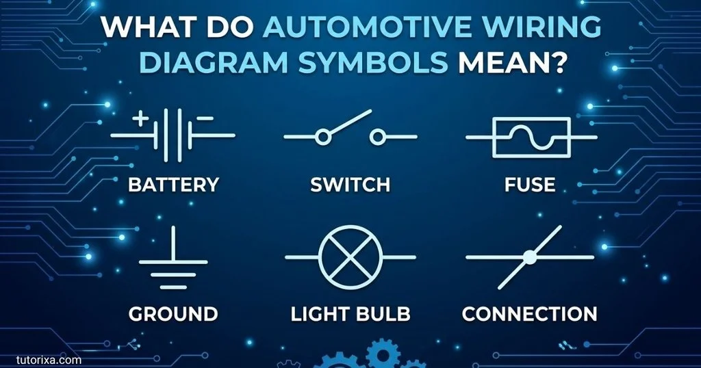
Automotive wiring diagram symbols represent the electrical parts and relationships that make a vehicle function. They allow a technician to follow a circuit from its power source through its control devices and electrical loads to its return path.
Most vehicle circuits contain several basic elements.
1. Power Supply Symbols
Power supply symbols identify where electrical energy enters a circuit.
Battery: The battery supplies electrical power when the engine is off and supports starting. In conventional vehicles, the battery also works with the alternator and charging system when the engine runs.
Power supply connection: A diagram may use labels such as B+, BAT, or a specific voltage designation to identify a power connection. B+ commonly refers to a positive battery-related supply, although the precise circuit meaning depends on the diagram.
Ignition-switched power: Labels such as IGN may identify a supply that becomes active under a particular ignition-switch condition. Not every circuit follows the same arrangement, especially in modern vehicles with electronic power management.
These symbols help technicians identify the beginning of a circuit and determine when power should be present.
2. Protection Symbols
Protection symbols identify devices that reduce the risk of electrical damage.
A fuse contains a protective element designed to open when current exceeds its intended rating under specified conditions. A circuit breaker performs a related protective function and may reset, depending on its design.
A wiring diagram can show a fuse’s location, rating, or circuit designation. For example, a fuse might protect a power-window circuit from excessive current.
Never replace a fuse with a higher-rated one simply because the original keeps opening. Repeated fuse failure can indicate a short circuit, overloaded component, or another electrical fault.
3. Switching Symbols
Switch symbols show devices that control whether current can flow.
A simple switch may be shown in an open or closed position. An open switch interrupts the circuit, while a closed switch completes the relevant connection.
Automotive diagrams may include:
- Ignition switches
- Door switches
- Brake-light switches
- Window switches
- Multi-position switches
- Normally open and normally closed contacts
The words normally open and normally closed describe the contact’s specified normal state, which depends on the device and its documentation. They do not necessarily describe what happens while the entire vehicle is operating.
4. Relay Symbols
A relay symbol commonly includes a coil and one or more electrical contacts.
The coil creates a magnetic field when energized, causing the relay contacts to change state. In a conventional electromechanical relay, this allows a relatively small control current to operate a separate load circuit.
Relays may control devices such as cooling fans, fuel pumps, horns, and certain lighting circuits.
Common contact arrangements include:
- Normally open (NO): The contact is open in its defined unenergized state.
- Normally closed (NC): The contact is closed in its defined unenergized state.
- Changeover contact: A movable contact switches between alternative connections.
A relay’s physical pin layout and contact arrangement must be verified using the relevant diagram or relay specification.
5. Ground Symbols
Ground symbols identify a circuit’s electrical reference or return connection.
In many conventional vehicles, the metal chassis connects to battery negative and serves as part of the return path. However, some circuits use dedicated return wires, isolated connections, or electronic reference grounds.
Different ground symbols can represent chassis ground, signal ground, or a designated reference point. These are not always interchangeable.
For example, a sensor’s signal ground may connect to an electronic control module rather than directly to the vehicle body. Treating every ground as identical can lead to incorrect diagnoses.
6. Electronic Component Symbols
Modern vehicles contain electronic circuits that control engine operation, safety systems, comfort features, and driver assistance.
Their diagrams may include symbols for resistors, capacitors, diodes, transistors, sensors, and integrated electronic modules.
The symbol indicates the type of component or connection, while the surrounding circuit explains its role.
For instance, a temperature sensor may provide a changing electrical signal to an engine control module. The module interprets that signal and uses it as one input when controlling engine operation.
History and Origin of Automotive Wiring Diagram Symbols
Automotive wiring diagram symbols developed from broader electrical engineering and industrial drafting conventions.
Early Electrical Diagrams
Before automobiles became common, electrical diagrams were already being used to explain telegraph systems, lighting circuits, motors, and other electrical equipment.
Engineers needed a compact visual language that could represent connections without drawing every component in realistic detail. Over time, schematic conventions emerged for batteries, switches, resistors, coils, and other electrical elements.
These conventions made it easier to document circuits and communicate designs between engineers and technicians.
The Growth of Automotive Electrical Systems
Early automobiles had relatively simple electrical systems compared with modern vehicles. As manufacturers introduced electric lighting, starters, generators, radios, and more sophisticated instruments, wiring diagrams became increasingly important.
Each additional electrical feature introduced new connections and potential failure points. Schematic drawings helped mechanics understand the relationships between power sources, switches, protective devices, and loads.
Standardization and Manufacturer Differences
Electrical drafting standards developed through professional and standards organizations. Examples include IEC publications for electrical graphical symbols and standards used in engineering documentation.
Automotive manufacturers also created service-manual conventions to match their own wiring harnesses, connectors, component names, and diagnostic procedures.
Consequently, two diagrams may represent the same general function with slightly different symbols, labels, or connector arrangements.
The Modern Automotive Era
Today’s vehicles combine conventional electrical wiring with computer-controlled systems, communication networks, and high-voltage equipment in electric and hybrid vehicles.
Wiring diagrams may therefore include conventional components alongside network connectors, electronic modules, shielded cables, and communication bus lines.
The fundamental purpose remains the same: to show how components connect and how a system is intended to function.
Symbolism and Interpretation of Automotive Wiring Diagrams
Automotive electrical symbols are primarily technical representations, not cultural or religious symbols. Their meaning comes from engineering conventions and the role they play in a circuit.
Traditional Electrical Meanings
Some electrical symbols represent physical components, such as a battery or lamp. Others represent electrical behavior, such as resistance, switching, or one-way current flow.
A resistor symbol, for example, identifies a component designed to provide resistance. A diode symbol identifies a device that conducts preferentially in one direction under normal operating conditions.
The diagram’s connections determine how these components work together.
Modern Electronic Meanings
In modern automotive diagrams, a component may be represented by a simple symbol, a labeled rectangle, or a functional block.
An engine control module might appear as a box with multiple terminals rather than a collection of individual electronic components. This approach simplifies a complex system while preserving the information needed to understand external connections.
Why Context Matters
A line, arrow, dot, or rectangle can have different meanings depending on the drawing convention.
For example, a line may represent a wire, a dashed boundary may group components, and a dot at an intersection may indicate an electrical connection. However, line styles and junction conventions are not identical in every schematic.
A technician should never rely on the shape alone when a legend or component label is available.
Cultural and Industry Significance of Automotive Wiring Symbols
Automotive wiring symbols are part of an international technical language used by vehicle manufacturers, repair professionals, engineers, and students.
Symbols Across Countries
Vehicles sold in the United States, Europe, Japan, South Korea, and other markets may use related electrical conventions. Nevertheless, terminology, connector references, wire-color systems, and diagram layouts can differ.
A symbol in an American service manual may be accompanied by a different label or wire-color abbreviation in a European manual.
These differences reflect the standards and documentation practices used by manufacturers and markets rather than cultural symbolism in the traditional sense.
Automotive Education
Students in automotive technology programs learn wiring symbols to connect classroom theory with practical electrical diagnosis.
Recognizing a fuse, relay, switch, or ground symbol helps students understand how a circuit should operate before using diagnostic equipment.
This knowledge also supports safer troubleshooting because technicians can identify power sources, protective devices, and sensitive electronic connections.
Scientific and Technical Meaning of Automotive Wiring Symbols
Automotive wiring symbols are grounded in electrical engineering. Their meanings become clearer when considered in terms of voltage, current, resistance, and circuit behavior.
Voltage, Current, and Resistance
Three basic electrical concepts help explain many automotive circuits:
- Voltage: The electrical potential difference that can drive current through a circuit.
- Current: The rate at which electric charge flows.
- Resistance: The opposition a component or material presents to current.
These concepts help technicians interpret diagrams and understand why a circuit may fail even when its components appear intact.
Wire and Connection Symbols
A wire is usually represented by a line. Labels may identify the wire’s color, gauge, circuit number, or destination.
A connection dot may indicate that intersecting conductors are electrically joined. In other conventions, crossing lines without a junction mark may indicate that the wires are not connected.
Always verify the drawing’s conventions before interpreting crossings and junctions.
Resistor and Variable Resistor Symbols
A resistor limits current or establishes a voltage relationship within a circuit.
A variable resistor includes an adjustment mechanism or changing resistance value. Certain sensors use a variable-resistance principle, although many modern automotive sensors rely on other technologies.
A symbol that resembles an adjustable resistor should be interpreted using the component label and manufacturer’s documentation.
Diode and LED Symbols
A diode conducts preferentially in one direction under normal forward-bias conditions and blocks current in the reverse direction within its rated limits.
A light-emitting diode, or LED, produces light when current flows through it in the appropriate direction.
These components appear in vehicle electronics, lighting systems, protection circuits, and electronic control modules.
Sensors and Control Modules
Automotive sensors measure or detect conditions such as temperature, pressure, rotational speed, position, and oxygen concentration.
Their signals may be analog, digital, frequency-based, or communicated over a vehicle network.
Control modules process sensor information and manage outputs. Because a simplified wiring diagram may not show every internal circuit, the diagram should be read alongside the relevant technical description.
High-Voltage Hybrid and Electric Vehicles
Hybrid and electric vehicles include high-voltage battery systems, inverters, electric motors, and dedicated safety components.
Their diagrams may use special labels, cable markings, connector representations, and warnings to distinguish high-voltage equipment from conventional low-voltage circuits.
High-voltage systems can present serious shock and arc hazards. Never use a general wiring-symbol guide as a substitute for manufacturer-approved training and isolation procedures.
Where Automotive Wiring Diagram Symbols Are Used
Automotive wiring symbols appear in several important technical and educational settings.
Vehicle Repair Manuals
Service manuals use wiring diagrams to show how components connect and where circuit branches, fuses, relays, and grounds are located.
These diagrams are particularly helpful when diagnosing a nonworking headlight, power window, horn, or starting circuit.
Automotive Electrical Schematics
Electrical schematics show the logical relationships between components. They help technicians understand the circuit’s intended behavior without reproducing the exact physical route of every wire.
A schematic is therefore different from a wiring-layout drawing, which may show the physical placement of harnesses and connectors.
Diagnostic Tools and Training Materials
Automotive education materials use symbols to explain circuit theory, measurement techniques, and troubleshooting methods.
Diagnostic procedures may direct a technician to measure voltage, check continuity, or inspect a connector at a specified terminal.
The diagram identifies the relevant circuit, while the service procedure explains the required test.
Vehicle Manufacturing and Engineering
Engineers use wiring documentation when designing electrical systems, developing prototypes, preparing production harnesses, and verifying component integration.
Clear symbols and labels reduce ambiguity during design reviews, manufacturing, maintenance, and later repairs.
Common Variations in Automotive Wiring Diagram Symbols
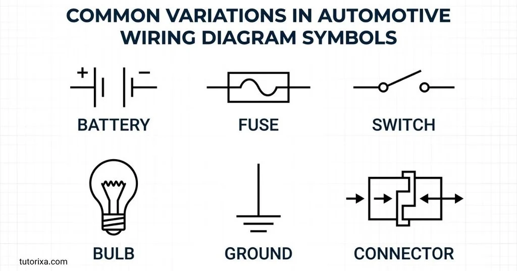
Automotive symbols can vary by standard, manufacturer, and document type.
Resistor Symbol Variations
Resistors may appear as a rectangular box or a zigzag line, depending on the drawing convention.
Both can represent a resistor, but readers should consult the legend to confirm the notation used in a particular diagram.
Ground Symbol Variations
A ground may be shown using a set of descending horizontal lines, a chassis-related mark, or a labeled ground point.
A diagram may also distinguish a sensor ground from a chassis ground. These distinctions can matter when measuring voltages or diagnosing electrical noise.
Connector and Splice Symbols
Connectors may appear as paired shapes, terminal blocks, or labeled connector identifiers. Splices may be marked with junction dots or specific splice references.
Some manufacturer diagrams include connector-face views that show pin numbers and the physical arrangement of terminals.
A schematic connection does not necessarily reveal the connector’s exact physical position or orientation.
Wire Color and Circuit Labels
Wire colors and abbreviations vary among manufacturers and markets.
A label may identify a wire using a color abbreviation, circuit number, or terminal designation. Some diagrams also specify wire gauge or shielding.
Never assume that the same color has the same function across every vehicle.
Common Misconceptions About Automotive Wiring Diagram Symbols
Misconception 1: Every manufacturer uses exactly the same symbols.
Many symbols follow common electrical conventions, but manufacturers can use different drawing styles, labels, and connector representations. Always consult the diagram legend.
Misconception 2: Every crossing wire is electrically connected.
A crossing may or may not represent a junction. Connection dots, line styles, and drawing conventions determine the intended meaning.
Misconception 3: A ground symbol always means the metal chassis.
Some diagrams distinguish chassis ground from electronic signal ground or dedicated return connections. Their functions should not be assumed to be identical.
Misconception 4: A wiring diagram shows the physical position of every wire.
A schematic primarily explains electrical relationships. Physical harness layouts and connector-location diagrams provide different information.
Misconception 5: Replacing a fuse with a larger one solves repeated fuse failures.
A higher-rated fuse may fail to protect the wiring adequately. Repeated failures require diagnosis of the underlying electrical problem, not simply a change in fuse rating.
Misconception 6: All automotive sensors work the same way.
Sensors use different operating principles and signal types. A resistance-based sensor, a Hall-effect sensor, and a digital network sensor require different interpretations and testing methods.
Misconception 7: A low-voltage wiring diagram is sufficient for every electric vehicle repair.
High-voltage systems require vehicle-specific safety procedures and appropriate training. A general schematic guide does not make high-voltage work safe.
10 Interesting Facts About Automotive Wiring Diagram Symbols
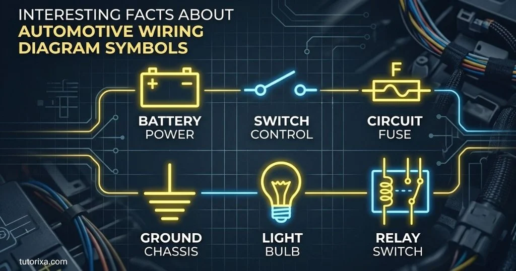
1. A schematic does not need to resemble the vehicle’s physical layout. Components may be placed wherever they make the electrical relationships easier to understand.
2. A single fuse can protect several branches. Some diagrams show a fuse supplying multiple downstream circuits, making it easier to identify which components could be affected by a blown fuse.
3. Ground connections are not always interchangeable. Separate reference grounds can be important to the accuracy of electronic sensor signals.
4. Relays separate control from load switching. A small control circuit can operate contacts that switch a different electrical load, depending on the relay’s design and ratings.
5. Connector numbers help identify individual terminals. Two connectors with similar shapes can have different pin assignments, making connector references essential during diagnosis.
6. Wire colors are documentation clues, not universal guarantees. Color conventions can vary by manufacturer, model year, market, and repair history.
7. Modern vehicles rely on electronic communication networks. Some components exchange information digitally rather than receiving a separate direct control wire for every function.
8. A wiring diagram can reveal shared electrical dependencies. If several components stop working at once, a shared fuse, ground, or supply may be relevant to the diagnosis.
9. LEDs have polarity-sensitive operation. Their direction and circuit arrangement matter, unlike a simple incandescent lamp in many conventional applications.
10. High-voltage vehicles require additional safety awareness. Hybrid and electric vehicle diagrams may distinguish hazardous high-voltage components from ordinary low-voltage circuits.
Related Symbols in Automotive Electrical Systems
Several related symbols help complete an automotive electrical reference.
| Related Symbol | Meaning | How It Differs |
| Battery symbol | Electrical energy source | Supplies power rather than protecting a circuit |
| Fuse symbol | Overcurrent protection | Opens a circuit when its protective element operates |
| Relay symbol | Electrically controlled switching | Uses a control mechanism to change contact state |
| Switch symbol | Manual or automatic circuit control | Directly represents a switching function |
| Ground symbol | Electrical reference or return | Identifies a connection rather than a load |
| Diode symbol | Direction-dependent conduction | Controls current direction within its operating limits |
| Motor symbol | Electromechanical energy conversion | Represents a load that produces motion |
| Sensor symbol | Measurement or detection | Provides information about a physical condition |
| Connector symbol | Detachable connection | Identifies a connection point between components or harness sections |
| Control module symbol | Electronic processing and control | Represents a system that interprets signals and controls outputs |
These symbols work together to describe the complete circuit. For example, a battery may supply power through a fuse and relay to a motor, while a switch or electronic module controls when the relay operates.
Frequently Asked Questions About Automotive Wiring Diagram Symbols
1. What are the most common automotive wiring diagram symbols?
The most common automotive wiring diagram symbols represent batteries, fuses, switches, relays, grounds, wires, connectors, lamps, motors, sensors, and control modules. These symbols help technicians understand circuit connections and functions. Their exact shapes may differ, so the legend in the vehicle’s service manual should always be treated as the primary reference.
2. How do I read an automotive wiring diagram?
Start by locating the diagram legend, battery or power source, protective devices, control components, electrical loads, and ground or return connections. Follow the lines and labels to understand how the circuit connects. Then use the relevant service procedure to identify test points, connector terminals, and expected electrical values.
3. What does a ground symbol mean in a car wiring diagram?
A ground symbol identifies an electrical reference or return connection. In many conventional vehicles, chassis ground connects to battery negative, but electronic circuits may use dedicated signal grounds or reference points. The exact meaning depends on the diagram, so do not assume that every ground symbol represents the same physical connection.
4. What does a relay symbol look like in an automotive schematic?
A relay is commonly represented by a coil and switching contacts, although drawing styles vary. The coil indicates the control portion, while the contacts show how the switched circuit connects in different states. Relay pin numbers and contact arrangements should be checked against the vehicle documentation or the relay’s own specification.
5. What is the difference between a wiring diagram and an electrical schematic?
A wiring diagram can emphasize the actual wiring, connectors, wire colors, and physical connections used in a vehicle. An electrical schematic emphasizes how components are electrically related and how the circuit functions. Automotive service manuals may combine both approaches, so check the drawing type before using it for physical component location.
6. Do automotive wiring diagram symbols follow international standards?
Many electrical symbols are based on established engineering conventions, including those published by IEC and other standards organizations. However, automotive manufacturers may add their own labels, connector references, and drawing conventions. For accurate interpretation, use the legend supplied with the particular vehicle’s wiring diagram.
7. What do wire colors mean in automotive wiring diagrams?
Wire colors help distinguish conductors and may be identified using abbreviations or labels in the diagram. Their meaning depends on the manufacturer’s wiring conventions, model year, and market. A red wire or black wire does not have one universal function across all vehicles, so always verify the circuit designation before testing.
8. Why are automotive wiring diagram symbols important for troubleshooting?
Symbols help technicians identify likely power paths, protection devices, switching components, loads, and ground connections. This makes it easier to narrow down where a circuit may be failing. Combined with the correct service procedure and electrical measurements, a wiring diagram supports systematic diagnosis rather than guesswork or unnecessary parts replacement.
9. Are automotive wiring diagrams the same for electric and gasoline vehicles?
No. Both vehicle types use low-voltage circuits and electronic controls, but electric and hybrid vehicles also include high-voltage batteries, inverters, traction motors, and related safety components. Their diagrams may contain additional symbols, cable markings, and warnings. High-voltage diagnostics require vehicle-specific procedures and appropriate training.
10. Where can I find accurate automotive wiring diagram symbols for my car?
The best starting point is the official service information for your vehicle’s make, model, year, and powertrain. Manufacturer documentation provides the relevant legend, connector views, wire identifiers, and diagnostic procedures. Reputable automotive repair databases may also offer model-specific diagrams, but generic symbol charts cannot replace vehicle-specific information.
Key Takeaways
- Automotive wiring diagram symbols represent electrical components, connections, and circuit functions.
- Batteries, fuses, switches, relays, grounds, connectors, sensors, and motors are among the most common symbols.
- Electrical symbols follow many shared conventions, but automotive manufacturers may use different labels and drawing styles.
- A wiring schematic explains electrical relationships, while a physical wiring layout helps identify actual harness locations.
- Wire colors, connector pin numbers, and ground designations must be interpreted using vehicle-specific documentation.
- Repeated fuse failures require diagnosis of the underlying fault rather than installing a larger fuse.
- Modern automotive diagrams include electronic modules and communication networks in addition to traditional wiring.
- Hybrid and electric vehicles require additional precautions when working with high-voltage components.
- The diagram legend and official service manual are the most reliable references for identifying unfamiliar symbols.
Conclusion
Automotive wiring diagram symbols provide a practical visual language for understanding vehicle electrical systems. From simple batteries and fuses to sophisticated sensors and electronic control modules, each symbol helps explain how components connect and interact.
Learning these symbols can make service manuals easier to understand, support automotive education, and help you follow electrical troubleshooting procedures more systematically. The key is to interpret each symbol in context, trace the relevant connections, and confirm its meaning using the manufacturer’s documentation.
Whether you are studying basic automotive electricity or learning how modern vehicle electronics work, understanding automotive wiring diagram symbols is an essential foundation for accurate electrical diagnosis and informed vehicle maintenance.

I’m Ellis Montgomery, a British writer interested in the powerful language of symbols. I explore everything from traditional emblems and cultural signs to contemporary symbols found in modern life. My aim is to explain their meanings clearly while revealing the stories and ideas behind them, making symbolism fascinating and accessible to everyone.
Books:
- The Complete Book of Symbols
- Hidden Messages in Everyday Symbols
 Freddie Beaumont
 Rowan Whitaker