
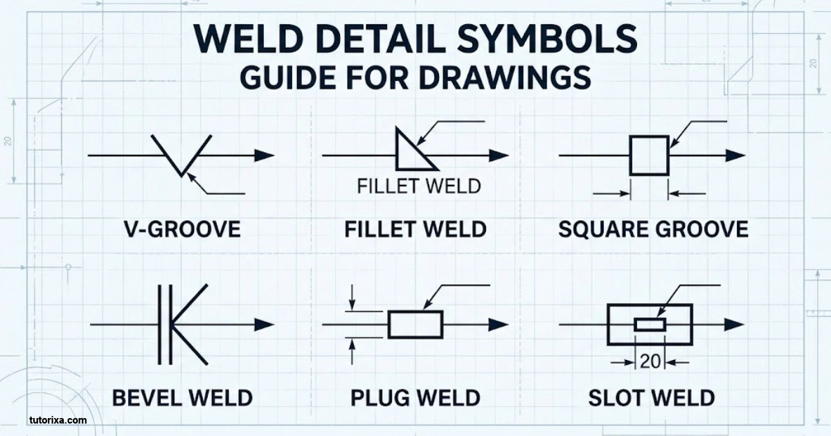
Weld detail symbols are used in engineering drawings, fabrication plans, and construction documents to show how different metal parts should be joined. They help welders understand the type of weld, its size, location, shape, and other important details before starting a job. Learning these symbols makes technical drawings easier to read and reduces confusion during fabrication.
Different welding symbols represent different joint types and welding methods. Some of the most common examples include fillet weld symbols, butt weld symbols, groove weld symbols, and finishing symbols. Each has a specific purpose and communicates information that cannot always be explained clearly with a written note.
If you are learning to read welding blueprints or working with steel fabrication drawings, understanding these symbols is essential. This guide explains common weld detail symbols, their meanings, and how they appear in technical drawings, with practical examples to help you recognize them.
Weld detail symbols and meanings
Weld detail symbols are graphical instructions used on engineering and fabrication drawings. They communicate the welding requirements for a particular joint, helping welders understand what type of weld is needed and how it should be completed.
A complete welding symbol can contain several parts. Each part provides different information about the required weld.
Main parts of a welding symbol
| Symbol part | Meaning |
| Arrow | Points to the joint that needs welding. |
| Reference line | Provides a base for placing welding information. |
| Basic weld symbol | Identifies the required type of weld. |
| Dimensions | Show weld size, length, pitch, or other measurements. |
| Tail | Provides additional information, such as a welding process or specification. |
| Supplementary symbols | Show details such as contour, finish, or field welding. |
The arrow connects the welding instruction to the location on the drawing. The reference line carries the weld symbol and related dimensions.
Under the widely used AWS A2.4 system, the position of a weld symbol in relation to the reference line helps identify which side of the joint requires welding.
Common weld symbols and their meanings
Here are some common basic welding symbols found in fabrication drawings.
| Weld symbol | Weld type | Meaning |
| △ | Fillet weld | Joins two surfaces at an angle. |
| □ | Square groove weld | Uses square joint edges. |
| V | V-groove weld | Uses a V-shaped groove. |
| ½V | Bevel groove weld | Uses a bevel on one joint edge. |
| U | U-groove weld | Uses a U-shaped groove. |
| J | J-groove weld | Uses a J-shaped groove. |
| ○ | Plug or slot weld symbol varies by representation | Identifies a plug or slot weld when shown in the appropriate symbol format. |
The triangle shown here is a simplified visual representation of the fillet weld symbol. In formal welding drawings, the exact symbol shape and placement should follow the applicable standard.
Supplementary welding symbols
Some symbols provide extra information about how a weld should look or where it should be performed.
| Symbol | Name | Meaning |
| ○ at arrow-reference junction | All-around weld | Weld around the entire joint. |
| Flag at junction | Field weld | Weld at the job site rather than the shop. |
| Straight contour | Flush or flat contour | Requires a flat weld surface. |
| Convex contour | Convex contour | Requires an outward-curved weld surface. |
| Concave contour | Concave contour | Requires an inward-curved weld surface. |
Remember that a welding symbol is not always the same as a complete welding instruction. Dimensions, notes, specifications, and process requirements may also be necessary to understand the full job.
All welding symbols

All welding symbols form a visual language used by engineers, welders, inspectors, and fabricators. They help communicate different weld types and joint requirements without writing lengthy instructions on every drawing.
The following categories cover many of the common symbols used in welding documentation.
Basic weld symbols
| Weld type | Description |
| Fillet weld | Joins two surfaces that meet at an angle. |
| Square groove weld | Uses square edges on the joint. |
| V-groove weld | Uses a V-shaped opening between joint edges. |
| Bevel groove weld | Uses one beveled edge. |
| U-groove weld | Uses a U-shaped groove. |
| J-groove weld | Uses a J-shaped groove. |
| Flare-V groove weld | Joins rounded surfaces using a V-shaped groove. |
| Flare-bevel groove weld | Joins a rounded surface to a flat or beveled surface. |
| Plug weld | Fills a hole in one member to join it to another. |
| Slot weld | Fills an elongated opening to connect overlapping members. |
| Spot weld | Creates a localized weld between overlapping surfaces. |
| Seam weld | Produces a continuous or intermittent welded seam. |
| Stud weld | Attaches a stud or similar component to a surface. |
| Surfacing weld | Deposits weld metal onto a surface to build it up or improve its properties. |
Supplementary welding symbols
Supplementary symbols provide additional information about the finished weld.
- All-around weld: Indicates that welding must continue around the entire joint.
- Field weld: Shows that welding should take place at the construction or installation site.
- Flush contour: Indicates a flat weld surface.
- Convex contour: Indicates an outward-curved weld surface.
- Concave contour: Indicates an inward-curved weld surface.
- Backing or back weld information: Provides additional details about weld preparation and reinforcement where specified.
Weld dimensions and other details
Welding drawings may also include measurements and special instructions.
| Detail | What it communicates |
| Weld size | Required weld dimensions. |
| Weld length | Length of the weld. |
| Pitch | Distance between intermittent welds. |
| Root opening | Gap between joint edges before welding. |
| Groove angle | Angle of the prepared groove. |
| Depth of preparation | How deeply the joint edges are prepared. |
| Finish notation | Required weld surface finishing method. |
These details are especially useful in structural steel fabrication, pressure vessels, machinery, and other applications where weld quality and dimensions matter.
Fillet weld symbol

The fillet weld symbol is one of the most frequently used welding symbols in engineering drawings. It represents a weld that joins two metal surfaces meeting at an angle, usually at approximately 90 degrees.
Fillet welds are common in T-joints, lap joints, and corner joints. They are widely used in steel structures, frames, brackets, machinery, and fabrication work.
What does the fillet weld symbol look like?
The basic fillet weld symbol is a small right triangle placed on the reference line.
Copyable visual symbol: △
This triangle is a simplified text representation. The official welding symbol should be read from a standards-compliant drawing because its orientation and placement matter.
Fillet weld symbol positions
The position of the fillet weld symbol indicates which side of the joint requires welding.
| Symbol placement | Meaning |
| Below reference line | Arrow-side fillet weld. |
| Above reference line | Other-side fillet weld. |
| Both above and below | Fillet weld on both sides. |
Fillet weld dimensions
Fillet weld symbols can include measurements to show the required weld size and length.
For example, a drawing might show:
- 6: A 6 mm fillet weld size.
- 50: A weld length of 50 mm.
- 100: A pitch of 100 mm when specified in the intermittent-weld format.
A drawing may also include a length and pitch to specify a series of intermittent fillet welds rather than one continuous weld.
Common applications of fillet welds
Fillet welds are commonly used for:
- Connecting steel plates in T-joints.
- Joining overlapping metal sheets.
- Attaching brackets to structural frames.
- Connecting support members.
- Fabricating metal frames and equipment.
The correct fillet weld size depends on the design requirements, material thickness, loading conditions, and applicable welding standards.
Butt weld symbol
A butt weld joins two metal pieces positioned in approximately the same plane, with their edges meeting at a common joint. It is widely used in pipelines, steel structures, pressure vessels, tanks, and metal fabrication.
In technical drawings, butt welds are generally represented using groove weld symbols. The symbol indicates the type of groove preparation required before welding.
Common butt weld symbols
Different groove shapes are used depending on the material thickness, joint design, and welding requirements.
| Symbol representation | Weld type | Description |
| □ | Square groove | Uses square edges without a prepared bevel. |
| V | V-groove | Both edges are prepared to create a V-shaped opening. |
| ½V | Bevel groove | One edge is beveled to create the groove. |
| U | U-groove | Uses curved edges to create a U-shaped opening. |
| J | J-groove | One edge is prepared with a J-shaped profile. |
Types of butt joints
1. Square butt joint
Both metal edges remain square. This preparation may be suitable for thinner materials and specific joint designs.
2. Single V butt joint
Both edges are beveled to form a V-shaped groove. Weld metal fills the prepared space.
3. Double V butt joint
Both sides of the joint have V-shaped grooves. This preparation can help distribute welding work between both sides.
4. Single bevel butt joint
One edge is beveled while the other remains square. It is useful in certain joint configurations where access is limited.
What information does a butt weld symbol provide?
A butt weld symbol can communicate:
- Groove type.
- Groove angle.
- Root opening.
- Depth of preparation.
- Required weld size or effective throat.
- Backing or back weld requirements.
- Welding on one side or both sides.
Not every drawing includes all these details. The engineer specifies the information needed for the particular joint.
Steel weld detail symbols
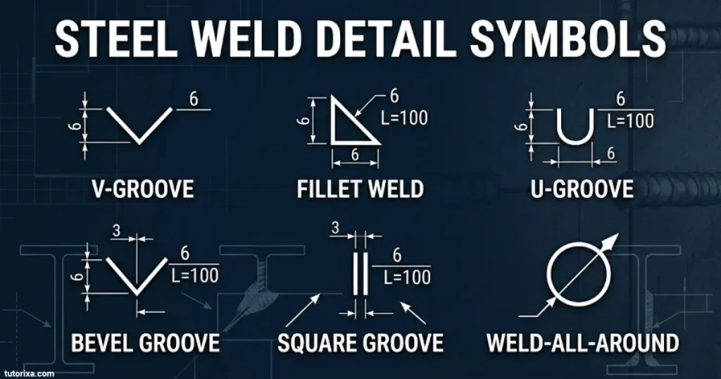
Steel weld detail symbols are used in structural steel drawings to explain how beams, columns, plates, braces, and other steel components should be connected.
These symbols help fabricators understand the required weld type, size, position, and length. They also help inspectors check whether completed welds meet the drawing requirements.
Common welding symbols in structural steel drawings
| Symbol or notation | Application |
| Fillet weld | Connecting plates, angles, and structural members. |
| V-groove weld | Joining steel plates with prepared edges. |
| Bevel groove weld | Connecting members where one edge requires bevel preparation. |
| Plug weld | Joining overlapping steel components through holes. |
| Slot weld | Connecting overlapping plates using elongated openings. |
| All-around symbol | Indicating welding around the complete joint. |
| Field weld symbol | Identifying connections that must be welded on-site. |
Examples of steel welding details
Beam-to-column connections: Fillet and groove welds may be used to connect beams to columns. The drawing identifies the weld requirements for the specific connection.
Gusset plate connections: Gusset plates connect braces and other structural members. Welding symbols show where and how the plates must be attached.
Base plate connections: Steel columns are often connected to base plates using specified weld details. These instructions help ensure the connection matches the structural design.
Steel stiffeners: Stiffener plates may be welded to beams or columns to provide additional support. Fillet weld symbols commonly appear in these details.
How to read steel weld detail drawings
Follow these steps when reading a steel fabrication drawing:
- Locate the joint that needs welding.
- Follow the arrow to identify the connection.
- Read the basic weld symbol to determine the weld type.
- Check its position relative to the reference line.
- Review the dimensions for weld size, length, and pitch.
- Read any tail information, notes, or referenced welding specifications.
- Check whether the weld is required in the shop or at the construction site.
Important standards for steel welding symbols
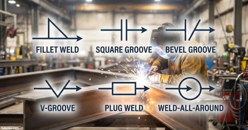
Two widely recognized standards are:
- AWS A2.4: Standard Symbols for Welding, Brazing, and Nondestructive Examination.
- ISO 2553: Welding and allied processes — Symbolic representation on drawings.
These standards provide systems for presenting welding information on technical drawings. Their conventions are not identical in every respect, so readers should identify which standard governs a particular project.
For structural steel work, always follow the approved engineering drawings, applicable project specifications, and relevant welding codes. Never determine a structural connection’s required weld size from a symbol illustration alone.
Frequently Asked Questions
What are weld detail symbols?
Weld detail symbols are graphical instructions on engineering drawings that identify weld types, dimensions, locations, and other welding requirements. They help welders understand how metal components should be joined.
What is the most common welding symbol?
The fillet weld symbol is one of the most commonly used welding symbols. It represents a triangular weld joining two metal surfaces that meet at an angle.
What is the difference between a fillet weld and a butt weld?
A fillet weld joins two surfaces that meet at an angle, such as a T-joint or lap joint. A butt weld joins two components positioned in approximately the same plane, usually along their edges.
What do the numbers on welding symbols mean?
Numbers can indicate weld size, length, pitch, groove angle, or other dimensions. Their meaning depends on their position and the type of weld symbol used.
What standards are used for welding symbols?
AWS A2.4 and ISO 2553 are two widely recognized standards for welding symbols on technical drawings. The applicable standard should be identified before interpreting a drawing.
Conclusion
Weld detail symbols make engineering and fabrication drawings easier to understand. They communicate important information about weld types, joint preparation, dimensions, and welding locations. Learning the basic symbols gives you a useful starting point for reading technical drawings.
Fillet welds, butt welds, groove welds, plug welds, and supplementary symbols each have different purposes. Recognizing these details can help you understand steel fabrication plans and identify the requirements for different metal connections.
Always check the drawing notes and applicable welding standards before starting fabrication. A correct understanding of welding symbols helps prevent mistakes and ensures that the completed work follows the approved design.

I’m Freddie Beaumont, a British author with a passion for discovering what symbols communicate without words. I write about their history, meanings, and everyday uses in an accessible way. I believe symbols tell fascinating stories about people, cultures, and ideas, and my work helps readers recognise and understand those stories more clearly.
Books:
- Symbols and Their Hidden Meanings
- Understanding Signs and Symbols
 Rowan Whitaker
 Ellis Montgomery