
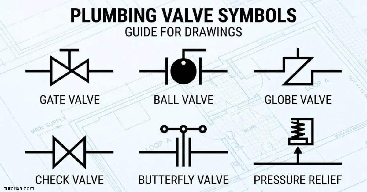
Plumbing valve symbols help you understand how water flows through a plumbing system and how different valves control that flow. You will find these symbols on plumbing drawings, construction plans, engineering diagrams, and building blueprints. Each symbol represents a component or function, such as opening and closing a pipe, preventing backflow, or regulating water pressure.
If you are learning to read plumbing plans, recognizing common valve symbols is a useful first step. A gate valve, ball valve, check valve, and control valve may serve different purposes, even when their symbols look similar. Understanding these differences can help you follow pipe routes, identify shutoff points, and interpret the information shown in technical drawings.
This guide covers plumbing valve symbols and meanings, common plumbing symbols, symbol charts and legends, residential and architectural drawings, and isometric diagrams. You will also learn how valve symbols appear on blueprints and how to work with plumbing symbols in Bluebeam. Because symbols can vary by drawing standard and project, always check the legend supplied with the specific plan you are reading.
Plumbing Valve Symbols and Meanings
Plumbing valve symbols are simplified graphical representations of valves used to control, direct, stop, or regulate fluid flow through pipes. Instead of drawing the full physical valve, a technical diagram uses a compact symbol that fits neatly into the piping layout.
The exact appearance of a symbol depends on the drawing convention, industry standard, and type of valve. The following table introduces common valve types and their usual functions.
| Valve type | Main function | Where it is commonly used |
| Gate valve | Starts or stops flow | Main water lines and isolation points |
| Ball valve | Provides quick shutoff | Water supply branches and equipment connections |
| Globe valve | Regulates flow | Systems that need flow adjustment |
| Check valve | Prevents reverse flow | Pump outlets and selected supply lines |
| Butterfly valve | Controls or isolates flow | Larger pipes and mechanical systems |
| Pressure-reducing valve | Lowers downstream pressure | Water supply systems |
| Pressure-relief valve | Releases excessive pressure | Protected equipment and pressurized systems |
| Float valve | Controls liquid level | Tanks and cisterns |
| Solenoid valve | Uses electrical actuation | Automatic plumbing and control systems |
| Balancing valve | Helps adjust flow distribution | Heating and chilled-water systems |
A valve symbol may include extra marks to show its operating method. For example, a line or stem can indicate an actuator or manual operating mechanism, while a small annotation may identify a motorized, pneumatic, or electrically operated valve.
Remember that the symbol alone may not tell you every detail. The valve’s tag, specification, nearby notes, and drawing legend often provide the information needed to identify the exact component.
Common Plumbing Symbols
Plumbing drawings contain more than valve symbols. They also use marks for pipes, drains, fixtures, fittings, equipment, and connections. Learning these related symbols makes it easier to understand the entire system rather than interpreting each valve in isolation.
Here are some common plumbing symbols and abbreviations you may encounter. These are simplified text representations or common labels, not universal substitutes for the official symbols on a drawing.
| Symbol or label | Meaning | Typical use |
| — | Pipe or line | Represents a pipe run in a simplified sketch |
| T | Tee connection | Shows a branch in a pipe |
| ELB | Elbow fitting | Identifies a pipe direction change |
| GV | Gate valve | Labels a gate valve |
| BV | Ball valve | Labels a ball valve |
| CV | Check valve | May identify a check valve |
| PRV | Pressure-reducing valve or pressure-relief valve, depending on context | Requires confirmation from the legend |
| FD | Floor drain | Marks a floor drainage point |
| CO | Cleanout | Indicates access for clearing a drain |
| WC | Water closet | Identifies a toilet |
| HB | Hose bibb | Marks an outdoor or utility hose connection |
| WH | Water heater | Identifies water-heating equipment |
Abbreviations can vary between projects. In particular, PRV can refer to different pressure-control devices depending on the industry and project documentation. Never rely on an abbreviation alone when the distinction affects installation or safety.
A plumbing drawing may also distinguish cold-water, hot-water, sanitary drainage, vent, and stormwater lines using line styles, colors, or labels. These conventions should be verified against the project legend instead of assumed.
Plumbing Symbols Chart
A plumbing symbols chart provides a quick reference for identifying the symbols used throughout a drawing set. It is especially helpful when you need to compare several valve types or locate a particular fitting without reading lengthy technical notes.
The chart below combines common valve names with simplified schematic representations. These representations are conceptual rather than standardized drafting symbols, so use the project drawing and its legend to confirm the actual graphical form.
| Valve or component | Simplified representation | Meaning |
| Gate valve | —◇— | Isolation by a gate mechanism |
| Ball valve | —○— | Quick shutoff using a rotating ball |
| Check valve | —▷— | Permits flow in one direction; verify the specified symbol |
| Globe valve | —◁▷— | Flow regulation in common schematic conventions |
| Butterfly valve | —◉— | Isolation or flow control using a rotating disc |
| Pressure-reducing valve | —[PR]— | Reduces downstream pressure; label is illustrative |
| Pressure-relief valve | —[RV]— | Releases pressure under specified conditions |
| Solenoid valve | —[SV]— | Electrically actuated valve |
| Balancing valve | —[BAL]— | Adjusts flow to help balance a system |
| Shutoff valve | —[S]— | General isolation point in this illustrative chart |
How to use the chart: Match the valve on your plan to the relevant symbol in the official legend. Then check its label, flow direction, and any actuator or control notes. If the drawing includes a valve schedule, use that schedule to verify the model, size, and specification.
For copying and sharing, the text labels in this chart are easy to reuse in notes or digital documents. The schematic marks are only visual aids; they should not be copied into construction documents as approved engineering symbols without verification.
Plumbing Symbols Legend
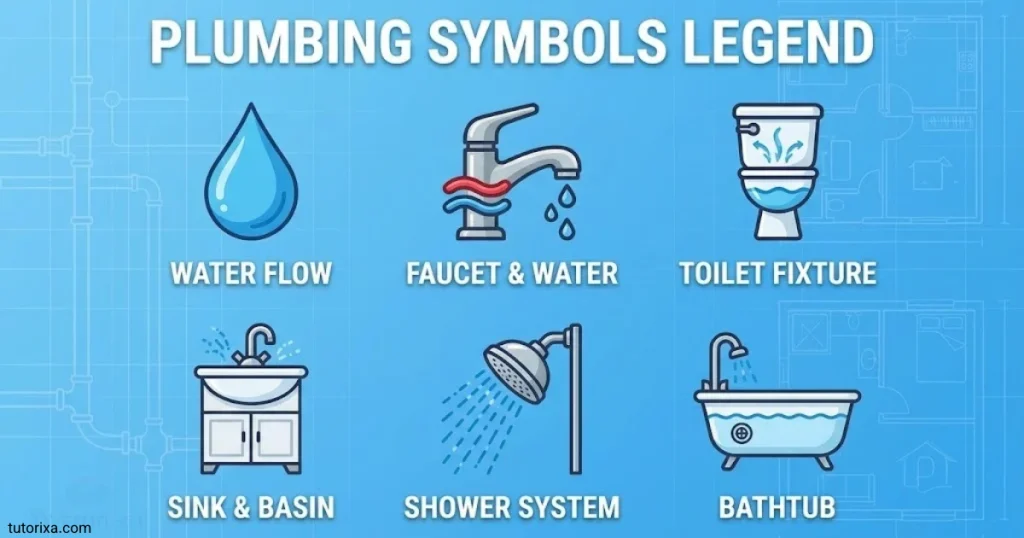
A plumbing symbols legend explains the symbols, abbreviations, and line conventions used in a particular set of drawings. It acts as a key, allowing contractors, designers, inspectors, and other readers to interpret the plans consistently.
A typical legend may contain the following categories:
- Valves: Gate valves, ball valves, check valves, control valves, and pressure-control devices.
- Pipes: Cold-water supply, hot-water supply, sanitary drainage, vent lines, and stormwater piping.
- Fittings: Tees, elbows, reducers, unions, and other pipe connections.
- Fixtures: Toilets, sinks, showers, bathtubs, and floor drains.
- Equipment: Pumps, water heaters, tanks, filters, and backflow prevention assemblies.
- Controls: Sensors, actuators, thermostats, and automatic control devices.
- Abbreviations: Short labels used to identify equipment, pipe services, and valve types.
How To Read A Plumbing Legend
Start by finding the legend, which is often placed near the beginning of a drawing set or on a general notes sheet. Locate the symbol that matches the one shown on the plumbing plan.
Next, read its description and any associated abbreviation. If the symbol has a tag, find that tag in the valve schedule or equipment schedule. Finally, check the relevant notes for special requirements.
A legend can also identify conventions that are not obvious from a symbol alone, such as whether a line is existing or proposed, whether a valve is normally open or normally closed, or whether an actuator is included.
Practical tip: If a valve symbol does not match the examples you know, do not automatically assume the drawing is wrong. The designer may be using a different standard or a project-specific symbol.
Plumbing Symbols on Drawings
Plumbing symbols on drawings communicate how a plumbing system is arranged and how its components connect. Depending on the drawing, you may see a building layout, a schematic diagram, a riser diagram, or a detailed mechanical plan.
Valve symbols are commonly placed along pipe routes where a particular control or isolation function is required. Their positions help readers understand where a component belongs in the system.
For example, a simplified water supply drawing might show a main line entering a building, a shutoff valve near the entry point, branches leading to fixtures, and additional valves near equipment that may require maintenance.
When reading plumbing drawings, check these details:
- Pipe connections: Follow the lines to determine which components are connected.
- Valve placement: Identify where a valve isolates or controls a section of the system.
- Flow direction: Look for arrows, check-valve orientation, or other flow indicators.
- Component tags: Match labels to the valve schedule or equipment list.
- Pipe sizes: Read the dimensions and notes to understand the specified pipe size.
- Drawing references: Check whether a detail, section, or another drawing provides additional information.
A valve shown beside a pump, tank, or fixture may have a different purpose from a valve on the main supply. Its function depends on the system design and the surrounding components.
Plumbing drawings can also include several views of the same system. A floor plan shows the horizontal arrangement, while a riser or schematic can clarify vertical connections and system relationships.
Plumbing Symbols on Plans
Plumbing symbols on plans show where pipes, valves, fixtures, and equipment are located within a building or site. These drawings are often viewed from above, making it possible to understand the layout in relation to walls, rooms, and structural elements.
A floor plan may show a water supply valve inside a utility room, a shutoff point near a water heater, or a valve serving a particular group of fixtures. Drainage plans may use a different set of symbols to show cleanouts, traps, and drainage connections.
What To Check On A Plumbing Plan
- Location: Identify the room, wall, or equipment area where the valve is placed.
- Service line: Confirm whether the pipe carries hot water, cold water, drainage, or another service.
- Access: Check whether the valve needs an accessible location for operation or maintenance.
- Connections: Follow the branch to understand which fixtures or equipment it serves.
- Notes and dimensions: Use the plan’s annotations to confirm placement and sizing.
A floor plan does not always show the full installation detail. For instance, it may indicate a valve’s approximate location without showing the exact mounting height or connection arrangement. Those details may appear on a plumbing detail sheet, elevation, or specification.
Do not assume that two valves shown close together have the same function. Their labels and the connected pipework provide the better evidence.
Plumbing Symbols for Drawings
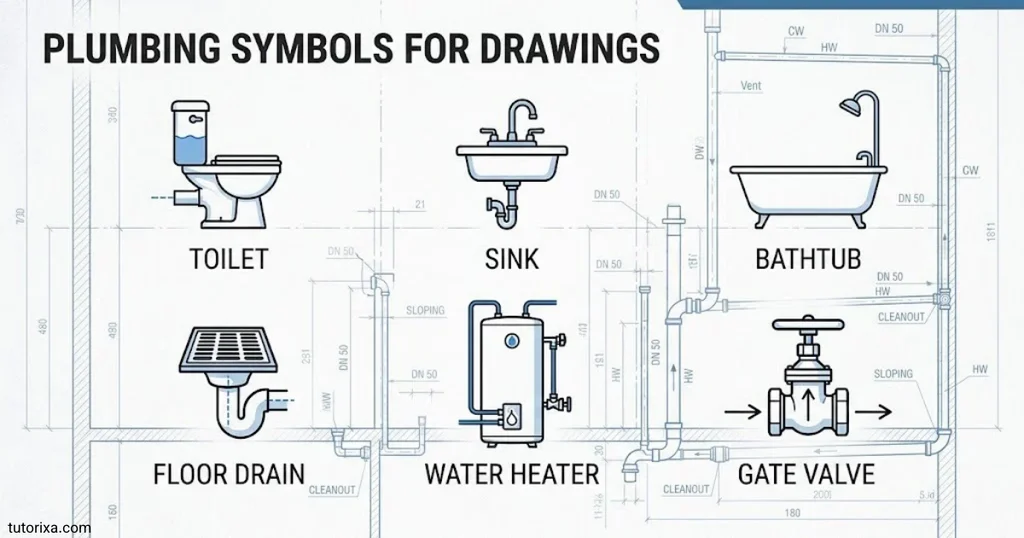
Plumbing symbols for drawings must be clear, consistent, and appropriate for the type of document being prepared. Designers use standardized drafting conventions where applicable so that different professionals can interpret the system without relying on illustrations of the actual hardware.
When creating or reviewing a plumbing drawing, choose symbols that clearly distinguish one valve function from another. Avoid using the same mark for two different components unless the legend explicitly defines the convention.
A useful drawing should include:
- A readable symbol for each valve type.
- Clear abbreviations and component tags.
- Pipe lines that show the system connections.
- Flow arrows where direction matters.
- Notes for actuators, controls, and unusual operating conditions.
- A complete legend covering project-specific symbols.
- Consistent line weights, text sizes, and spacing.
Example Of A Simplified Plumbing Diagram
The following text sketch illustrates how a shutoff valve might appear in a simple supply route:
Water supply → Main shutoff valve → Branch pipe → Fixture
This is a conceptual flow sequence, not an approved plumbing drawing. A real design may require additional valves, fittings, pressure controls, backflow protection, and other components based on the system.
When using a computer-aided design (CAD) program, use the appropriate symbol library or approved project template. Check that symbols remain legible at the final printed scale, especially on crowded drawings.
Plumbing Symbols for Blueprints
Blueprint plumbing symbols help communicate the location and function of components before construction begins. A plumbing blueprint may form part of a larger architectural or engineering drawing package, so its symbols need to work with the project’s overall drafting conventions.
A typical blueprint may include supply pipes, drainage lines, vents, fixtures, valves, pumps, and water-heating equipment. It may also include schedules, general notes, connection details, and references to other drawings.
How To Identify Valve Symbols On Blueprints
First, locate the plumbing legend. Compare the valve mark on the blueprint with the symbol shown in that legend, then read its abbreviation or component tag.
Next, trace the connected pipes. This can help you distinguish a valve on a main supply from one serving an individual fixture or piece of equipment. If the valve has a directional requirement, check the flow arrow or the manufacturer’s installation information.
Finally, check the blueprint’s scale and related details. A small symbol on a general layout may represent a component whose actual size and installation requirements are documented elsewhere.
Blueprint symbols are not a replacement for written specifications. The drawing set should be reviewed as a whole before any installation or modification work begins.
Blueprint Plumbing Symbols Legend
A blueprint plumbing symbols legend is the reference key that explains the marks used on a plumbing blueprint. It may be included on a plumbing sheet, a general legend page, or a project-specific schedule.
The legend should make it possible to distinguish valves from fittings, fixtures, and other equipment without guessing. It may also explain line types, abbreviations, and symbols used only for a particular project.
| Legend item | Information it should communicate |
| Valve symbol | Valve type or function |
| Valve tag | Unique component identifier |
| Pipe line | Pipe service or system |
| Flow arrow | Intended direction of flow |
| Actuator mark | Operating or control mechanism |
| Fixture symbol | Type and location of plumbing fixture |
| Equipment mark | Pump, tank, heater, or other equipment |
| Abbreviation | Defined short form used on the drawings |
| Drawing reference | Location of a related detail or schedule |
Why The Blueprint Legend Matters
Different companies, design teams, and drawing standards may use different graphical conventions. A triangle, circle, diamond, or other mark should not be interpreted as a specific valve type solely because it resembles a symbol in another drawing set.
The project legend is the primary reference for project-specific meanings. If a symbol is missing, unclear, or inconsistent with the schedule, seek clarification from the responsible designer rather than making an unsupported assumption.
Residential Plumbing Symbols
Residential plumbing symbols are used in drawings for houses, apartments, and other living spaces. They help show how water reaches fixtures, how wastewater leaves the building, and where valves and plumbing equipment are located.
A residential plumbing plan may include kitchen sinks, bathroom fixtures, laundry connections, water heaters, hose bibbs, cleanouts, and main shutoff valves. The exact symbol set depends on the drawing type and the designer’s conventions.
| Residential component | Common label or notation | Purpose |
| Main shutoff valve | Often tagged MSV or described in the legend | Shuts off the building’s water supply |
| Gate valve | GV | Isolates a section of pipe |
| Ball valve | BV | Provides quick shutoff |
| Check valve | CV | Prevents reverse flow where specified |
| Water heater | WH | Identifies water-heating equipment |
| Water closet | WC | Identifies a toilet |
| Floor drain | FD | Marks a floor drainage point |
| Cleanout | CO | Provides access to a drain for cleaning |
| Hose bibb | HB | Identifies a hose connection |
| Pressure-reducing valve | PRV in many drawings | Reduces water pressure when required |
These abbreviations are common examples, not universal standards. Confirm the meaning of each label against the residential drawing legend.
Where Residential Valve Symbols Appear
- Main water entry: A main shutoff valve may be shown where the water service enters the building.
- Water heater connections: Isolation valves may be included to support servicing.
- Fixture branches: Individual shutoff valves may be shown near sinks, toilets, and other fixtures.
- Outdoor water lines: Valves may control hose connections or irrigation branches.
- Special equipment: Filters, pumps, and pressure-control devices may have dedicated symbols.
The purpose of a residential plumbing plan is to communicate the system clearly enough for coordination, installation, and maintenance. Always use the approved drawings and applicable plumbing requirements when making actual installation decisions.
Architectural Plumbing Symbols
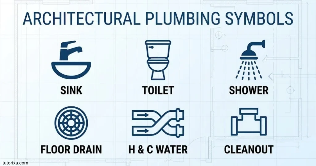
Architectural plumbing symbols help coordinate plumbing fixtures and services with the building’s layout. These symbols appear on architectural floor plans, bathroom layouts, kitchen plans, and related construction documents.
Architectural drawings often emphasize the location and arrangement of fixtures, while detailed plumbing or mechanical drawings may provide more information about pipes, valves, connections, and system operation.
Common architectural plumbing symbols and labels include:
| Symbol or label | Component | What it communicates |
| WC | Water closet | Toilet location |
| LAV | Lavatory | Bathroom sink location |
| SK | Sink | Sink location, as defined by the legend |
| SH | Shower | Shower location |
| FD | Floor drain | Drainage point |
| WH | Water heater | Equipment location |
| CO | Cleanout | Drain access point |
| HB | Hose bibb | Hose connection location |
The labels shown here are illustrative and may differ between architectural firms and project standards.
Architectural Vs. Plumbing Drawings
Architectural plans primarily communicate building arrangement, room use, fixture placement, and coordination with walls and other features. Plumbing drawings typically focus more closely on the piping system, valve locations, drainage connections, and equipment.
A valve may be absent from a simplified architectural plan even when it is required in the detailed plumbing design. That does not necessarily mean the valve is missing from the overall project. Check the relevant plumbing sheets and specifications for the complete arrangement.
Architectural symbols are especially useful when coordinating fixture placement with cabinetry, walls, access panels, and service areas. However, the architectural plan should not be treated as the sole source for detailed valve installation information.
Isometric Plumbing Symbols
Isometric plumbing drawings show piping in a three-dimensional-style view, making it easier to follow vertical and horizontal connections. They are particularly useful for risers, water supply arrangements, drainage systems, and complex pipe routes.
Unlike a typical floor plan, an isometric drawing can show how a pipe rises between floors, branches toward fixtures, or connects to equipment at different elevations.
Common symbols and labels found in isometric plumbing drawings include:
| Symbol or label | Meaning in context |
| GV | Gate valve |
| BV | Ball valve |
| CV | Check valve |
| PRV | Pressure-control valve; verify the intended type |
| TEE | Tee fitting |
| ELB | Elbow fitting |
| UP | Pipe continues upward, when defined by the drawing |
| DN | Pipe continues downward, when defined by the drawing |
| Ø | Diameter notation in applicable dimensioning conventions |
The abbreviations and marks must be interpreted according to the project’s legend. The symbol Ø, for example, is a diameter sign rather than a valve symbol.
How To Read An Isometric Plumbing Drawing
- Follow each pipe route from its source to its destination.
- Identify branches, bends, and vertical connections.
- Locate valves and read their tags.
- Check pipe sizes, elevations, and flow arrows.
- Refer to notes and schedules for components that are not fully described in the drawing.
Isometric diagrams can make valve placement easier to understand, but they do not always use true physical scale. Pipe lengths, angles, and component sizes may be simplified to improve readability.
For installation, use the stated dimensions, approved details, and relevant specifications rather than measuring distances directly from the isometric illustration.
Valve Symbols on Drawings
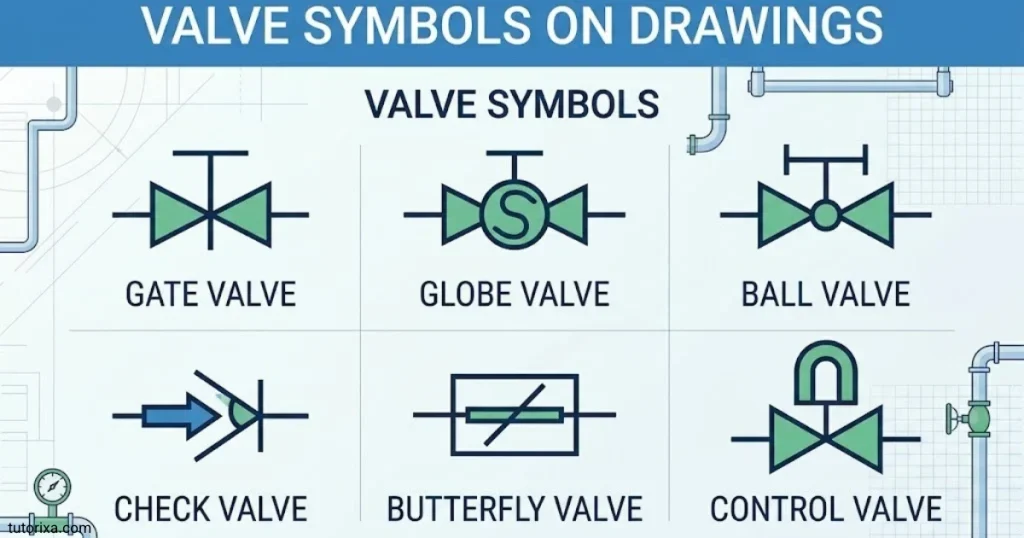
Valve symbols on drawings identify components that stop, start, regulate, or redirect flow. They may appear in plumbing, HVAC, industrial piping, fire protection, and process diagrams. Similar-looking symbols can have different meanings across these fields, so the drawing’s purpose and legend matter.
Some drawings use schematic marks that resemble two triangles meeting at their points to represent a general valve body. Additional lines, circles, or actuator marks may distinguish specific types. These are drafting conventions, not a universal symbol system.
Common Valve Symbol Features
- Valve body: The central shape indicates the location of the valve in the pipe.
- Stem or operating mark: May identify how the valve is operated.
- Actuator symbol: Can indicate electric, pneumatic, hydraulic, or other actuation.
- Flow arrow: Shows the intended direction of flow when direction is relevant.
- Tag or abbreviation: Links the symbol to a schedule or equipment description.
- Position annotation: May indicate a normally open, normally closed, or other specified operating state.
A valve symbol may also be shown alongside a control loop, pressure gauge, pump, or other equipment. These nearby marks can provide useful information about the valve’s role in the system.
Why Valve Symbols Can Differ
A plumbing plan, a P&ID (piping and instrumentation diagram), and an architectural drawing may use different symbol conventions. A P&ID often includes more information about control functions and instrumentation, while a residential plumbing plan may use a simpler representation.
For reliable interpretation, check the drawing legend first, then the valve schedule and technical notes. If a symbol’s meaning remains unclear, request clarification from the designer before using it to make installation or operational decisions.
Gate Valve Symbol
A gate valve controls flow by moving a gate or wedge into or out of the flow path. It is generally intended for isolation rather than frequent flow regulation.
The gate valve symbol varies with the drafting standard. Some piping diagrams show a valve body using opposing triangles, with additional features or a label identifying the gate mechanism. Other drawings may use a project-specific symbol.
Gate Valve Symbol Reference
Simplified text notation for identification, not a standardized CAD symbol
—◁▷—
Gate valve (illustrative)
For a technical drawing, use the symbol supplied by the applicable drafting standard or project legend.
What A Gate Valve Symbol Means
When a gate valve appears on a plumbing drawing, it generally identifies a point where a pipe section can be isolated. Its actual position and function depend on the system design.
Gate valves are commonly associated with:
- Main or branch isolation.
- Water distribution lines.
- Equipment maintenance arrangements.
- Larger piping systems where a full-bore opening may be desirable.
A gate valve is generally not the preferred choice for throttling because prolonged partial opening can damage the gate or seating surfaces, depending on the design.
Gate Valve Vs. Ball Valve
Both valve types can shut off flow, but they operate differently. A gate valve moves a gate through the flow path, while a ball valve rotates a bored ball. Ball valves are often selected when quick operation is useful.
To distinguish them on a drawing, do not rely only on the shape of a simplified symbol. Check the abbreviation, component tag, and valve schedule.
Ball Valve Symbol
A ball valve uses a rotating ball with a hole through its center to control flow. In a typical quarter-turn design, the ball rotates to align the opening with the pipe or turn it across the flow path.
Ball valves are widely used for water supply isolation because they can be operated quickly and generally provide a clear open-or-closed function.
Ball Valve Symbol Reference
Simplified text notation for identification, not an official universal symbol
—◇—
Ball valve (illustrative)
The diamond-like mark above is only a visual placeholder. Real drafting symbols vary by standard and project.
What A Ball Valve Symbol Means
A ball valve symbol usually identifies an isolation valve. Depending on the design and application, the valve may be installed on a main supply, branch pipe, equipment connection, or other service line.
Typical uses include:
- Shutting off water to a fixture or branch.
- Isolating a water heater or other equipment.
- Controlling supply to a maintenance area.
- Providing a manual shutoff in an accessible location.
The drawing may identify the valve as BV, but abbreviations vary. Confirm the designation in the legend.
How To Identify A Ball Valve On A Plan
Find the symbol and read any nearby label. If the plan uses tags, match the tag to the valve schedule. The schedule may specify the valve size, material, pressure rating, connection type, and operating mechanism.
A symbol by itself usually does not tell you whether the valve is full-port, reduced-port, suitable for a particular temperature, or approved for a particular service. Those details must come from the specifications.
Bluebeam Plumbing Symbols
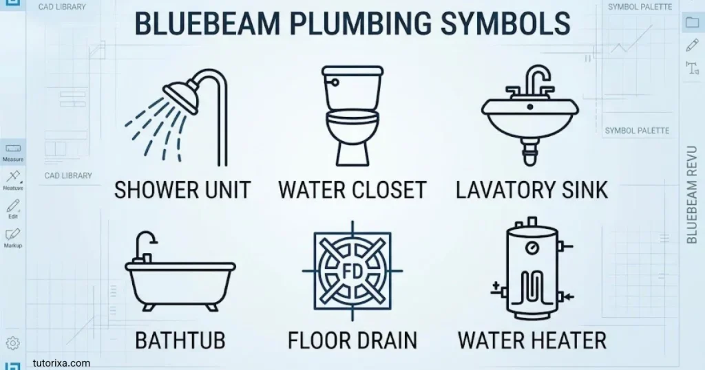
Bluebeam Revu is a PDF-based software application used in construction workflows to review, mark up, and coordinate drawings. It can help users work with plumbing symbols on digital plans, add annotations, and build reusable tool sets for common markups.
Bluebeam does not make every plumbing symbol universal. The symbol library or markup set used in a project should match the project’s drawing conventions and the needs of the people reviewing the documents.
How To Work With Plumbing Symbols In Bluebeam
1. Open the plumbing drawing. Load the relevant PDF and locate the sheet containing the plumbing layout, valve details, or symbol legend.
2. Review the existing legend. Identify the symbols and abbreviations already used in the drawing before adding markups. This helps prevent confusion between the original design and review annotations.
3. Use suitable markup tools. Depending on your workflow and Bluebeam version, you can use drawing tools, text, callouts, and reusable tool sets to mark valve locations or add review comments.
4. Create reusable symbols when needed. If your team repeatedly uses the same approved valve markups, you can create and organize reusable tool sets. Make sure each symbol is clearly named and documented.
5. Label important components. Use concise labels such as a project-approved valve tag or component name. Avoid relying on a visual symbol alone when the markup needs to communicate a specific technical requirement.
6. Check the final PDF. Review symbol placement, legibility, scale, and consistency before sharing the marked-up drawing.
Bluebeam Symbol Libraries And Tool Sets
A reusable tool set can save time when reviewing repeated components across multiple sheets. For example, a team may maintain separate tools for valve callouts, inspection comments, or coordination issues.
However, a review markup is not automatically part of the approved design. Keep the distinction clear between an existing engineering symbol, a proposed change, and a reviewer comment. Follow your team’s document-control process when modifying construction drawings.
For official software guidance, consult the Bluebeam Revu documentation for your installed version, since available tools and menu names may differ.
Frequently Asked Questions
What Are Plumbing Valve Symbols?
Plumbing valve symbols are graphical marks used on technical drawings to identify valves and their functions. They help readers locate shutoff points, flow-control devices, and other components within a piping system.
What Is The Difference Between A Gate Valve Symbol And A Ball Valve Symbol?
Both symbols identify valves used to control flow, but the valves operate differently. A gate valve uses a moving gate, while a ball valve uses a rotating ball. The exact graphical symbols depend on the drawing standard and project legend.
How Do I Read Plumbing Symbols On Blueprints?
Start with the plumbing legend, then identify the symbol, abbreviation, and component tag. Follow the connected pipe lines and check the valve schedule, dimensions, and notes to understand the component’s purpose.
Are Plumbing Symbols The Same In Every Drawing?
No. Symbols can vary by drafting standard, industry, software, and project requirements. Always use the legend supplied with the drawing instead of assuming that a symbol has the same meaning everywhere.
Can I Use Plumbing Symbols In Bluebeam Revu?
Yes. Bluebeam Revu supports PDF markups and reusable tools that can help you annotate plumbing drawings. Use approved symbol conventions, label your markups clearly, and distinguish review comments from the original design.
Conclusion
Plumbing valve symbols make technical drawings easier to understand by showing where valves and other components fit into a piping system. Learning the common meanings of gate valves, ball valves, check valves, and pressure-control devices helps you interpret plumbing layouts more confidently.
Plumbing charts, legends, residential plans, architectural drawings, and isometric diagrams each provide a different view of the system. Tools such as Bluebeam Revu can also help you review drawings and organize repeated annotations, provided the symbols follow the project’s conventions.
The most reliable approach is to identify the symbol, check its label, and confirm its meaning in the official drawing legend. This simple habit reduces confusion and helps you read plumbing plans more accurately, whether you are studying a blueprint or reviewing a construction document.

I’m Freddie Beaumont, a British author with a passion for discovering what symbols communicate without words. I write about their history, meanings, and everyday uses in an accessible way. I believe symbols tell fascinating stories about people, cultures, and ideas, and my work helps readers recognise and understand those stories more clearly.
Books:
- Symbols and Their Hidden Meanings
- Understanding Signs and Symbols
 Ellis Montgomery
 Rowan Whitaker