
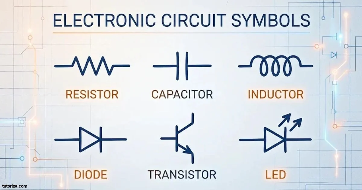
Electronic circuit symbols make it easier to understand how electrical and electronic components work together. Instead of drawing every component as it looks in real life, engineers use simple standard symbols to represent resistors, capacitors, batteries, switches, transistors, and other circuit parts.
If you are learning electronics, studying electrical engineering, or preparing a circuit diagram, knowing these symbols can save you time and help you understand different circuits. Each symbol represents a particular component or function, so recognizing it is an important basic skill.
In this guide, you will find electronic circuit symbols with their names, functions, and explanations. I have also included a collection of more than 100 common electrical and electronic symbols, a symbol chart, US symbol variations, and individual explanations of battery, cell, conductor, and bell symbols.
Basic Electronic Circuit Symbols
Electronic circuit symbols are simple graphical representations of components used in circuit diagrams. They show how different parts connect and what role each component plays in an electronic system.
Some symbols represent components that control electrical current, while others represent components that store energy, produce light, generate sound, or protect a circuit.
Here are some basic electronic circuit symbols beginners should recognize:
| Component | Simplified symbol representation | Main function |
| Resistor | ─/\/\/─ | Limits current |
| Capacitor | ─│ │─ | Stores electrical charge |
| Battery | ─┃│─┃│─ | Supplies electrical energy |
| Cell | ─┃│─ | Provides voltage |
| Switch | ─o/ o─ | Opens or closes a circuit |
| Diode | ─▷│─ | Allows current in one direction |
| LED | Diode symbol with outward arrows | Produces light |
| Inductor | ─∿∿∿─ | Stores energy in a magnetic field |
| Fuse | ─[ ]─ | Protects against excessive current |
| Ground | ⏚ | Provides an electrical reference |
| Lamp | Circle with a cross | Produces light |
| Motor | Circle with M | Converts electricity into motion |
Note: These are simplified text representations, not exact engineering drawings. The actual graphical shapes depend on the applicable schematic standard.
Why Are Basic Circuit Symbols Important?
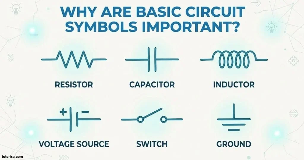
Learning basic symbols helps you:
- Read electronic circuit diagrams without confusion.
- Identify different components quickly.
- Understand how electricity moves through a circuit.
- Build and troubleshoot simple electronic projects.
- Communicate circuit designs with other people.
- Recognize components in textbooks, technical drawings, and engineering software.
You do not need to memorize every symbol at once. Start with resistors, capacitors, batteries, switches, and diodes before moving on to more advanced components.
Electronics Symbols With Names
Electronic components have different symbols, and each one has a specific name. Some symbols look similar, but they represent completely different components.
The following table provides a quick reference to commonly used electronics symbols and their names.
| Symbol name | Component | Common reference letter |
| Resistor | Resistor | R |
| Capacitor | Capacitor | C |
| Inductor | Inductor | L |
| Transformer | Transformer | T |
| Diode | Semiconductor diode | D |
| LED | Light-emitting diode | D |
| Zener diode | Zener diode | D |
| Transistor | such as of two minds transistor | Q |
| MOSFET | Metal-oxide-semiconductor transistor | Q |
| Battery | Battery | BT |
| Cell | Single electrical cell | B |
| Switch | Electrical switch | S |
| Fuse | Fuse | F |
| Relay | Electromagnetic relay | K |
| Motor | Electric motor | M |
| Lamp | Electric lamp | E |
| Speaker | Loudspeaker | LS |
| Buzzer | Sound-producing component | BZ |
| Bell | Electric bell | B |
| Ground | Ground connection | GND |
| Antenna | Antenna | ANT |
| Ammeter | Current-measuring instrument | A |
| Voltmeter | Voltage-measuring instrument | V |
| Oscillator | Signal oscillator | G |
| Integrated circuit | IC | U |
Reference letters are common conventions, not universal rules. They can vary between standards, industries, and individual drawing practices.
Common Electronic Component Categories
Electronic symbols can also be organized into categories based on their purpose.
- Passive components: Resistors, capacitors, inductors, and transformers.
- Active components: Transistors, integrated circuits, and semiconductor devices.
- Power sources: Cells, batteries, and voltage supplies.
- Switching components: Switches, relays, and push buttons.
- Protection components: Fuses, circuit breakers, and protective devices.
- Output components: Lamps, LEDs, speakers, motors, and buzzers.
- Measuring components: Ammeters, voltmeters, and other instruments.
These categories make it easier to find a component when reading or creating a schematic.
Electronic Circuit Symbols And Their Functions
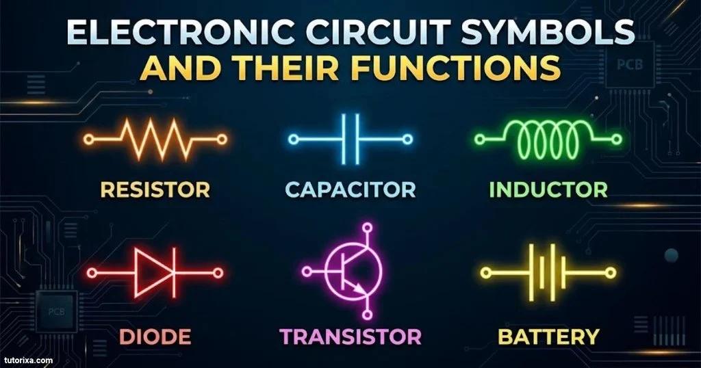
Every electronic circuit symbol represents a component with a particular job. Some components control current, others store energy, and some convert electrical energy into light, heat, or movement.
Understanding their functions is just as important as recognizing their shapes.
Here are some widely used electronic components and what they do.
1. Resistor
Symbol: ─/\/\/─ (US) or ─[ ]─ (IEC)
A resistor limits the flow of electrical current in a circuit. It is commonly used to protect sensitive components, control voltage, and divide electrical signals.
2. Capacitor
Symbol: ─│ │─
A capacitor stores electrical charge and releases it when needed. It is commonly used in power supplies, filters, timing circuits, and electronic signal systems.
3. Inductor
Symbol: ─∿∿∿─
An inductor stores energy in a magnetic field when current passes through its coil. It is often found in transformers, filters, and switching power supplies.
4. Diode
Symbol: ─▷│─ (simplified)
A diode allows current to flow primarily in one direction. It is used for rectification, reverse-polarity protection, and signal control.
5. Transistor
Symbol: Three-terminal semiconductor symbol
A transistor controls electrical current and can work as an electronic switch or amplifier. It is an essential component in computers, radios, and many other electronic devices.
6. Battery
Symbol: Alternating long and short parallel lines
A battery provides electrical energy to a circuit. Its symbol usually contains multiple cell pairs.
7. Switch
Symbol: ─o/ o─ (simplified)
A switch controls the flow of electricity by opening or closing a circuit. It is used in household devices, control panels, and electronic equipment.
8. LED
Symbol: Diode symbol with two outward arrows
An LED converts electrical energy into light. It is used in indicators, displays, lighting systems, and electronic products.
9. Fuse
Symbol: Fuse-specific series symbol
A fuse protects electrical circuits by breaking the connection when excessive current flows through it.
10. Transformer
Symbol: Two coil windings separated by core lines
A transformer transfers electrical energy between circuits through electromagnetic induction. It can increase or decrease AC voltage.
Why Component Functions Matter
Knowing what each component does helps you understand the complete circuit rather than simply memorizing its symbols.
For example, a basic LED circuit may contain a battery, resistor, LED, and connecting wires. The battery supplies energy, the resistor limits current, and the LED produces light.
All Electronic Circuit Symbols
Electronic circuit diagrams contain many different symbols. A simple circuit may need only a few components, while a complex electronic system can include dozens of symbol types.
Below is a categorized collection of commonly encountered symbols. It covers passive components, semiconductor devices, power sources, switching equipment, output devices, and measuring instruments.
Passive Component Symbols
| Component | Simplified appearance | Function |
| Fixed resistor | ─/\/\/─ | Limits current |
| Variable resistor | Resistor with diagonal arrow | Adjusts resistance |
| Potentiometer | Resistor with adjustable wiper | Controls voltage |
| Rheostat | Variable resistor | Controls current |
| Thermistor | Resistor with temperature marking | Responds to temperature |
| LDR | Resistor with incoming light arrows | Responds to light |
| Fixed capacitor | ─│ │─ | Stores charge |
| Polarized capacitor | Capacitor with polarity marking | Stores charge with polarity |
| Variable capacitor | Capacitor with diagonal arrow | Adjusts capacitance |
| Trimmer capacitor | Adjustable capacitor | Fine-tunes capacitance |
| Air-core inductor | Coil | Stores magnetic energy |
| Iron-core inductor | Coil with core lines | Stores magnetic energy |
| Transformer | Two coils with core lines | Transfers AC energy |
| Crystal | Crystal resonator symbol | Provides frequency stability |
| Varistor | Resistor with nonlinear marking | Protects against voltage surges |
Semiconductor Symbols
| Component | Simplified appearance | Function |
| PN diode | Diode with cathode bar | Controls current direction |
| Schottky diode | Schottky-specific diode symbol | Fast switching |
| Zener diode | Diode with bent cathode line | Voltage regulation |
| Tunnel diode | Special diode symbol | Negative-resistance operation |
| LED | Diode with outward arrows | Produces light |
| Photodiode | Diode with inward arrows | Detects light |
| Laser diode | Diode with outward light arrows | Produces laser light |
| Varactor diode | Diode with capacitor marking | Voltage-controlled capacitance |
| NPN transistor | Three-terminal transistor with outward emitter arrow | Switching and amplification |
| PNP transistor | Three-terminal transistor with inward emitter arrow | Switching and amplification |
| N-channel MOSFET | MOSFET symbol with gate and channel | Electronic switching |
| P-channel MOSFET | MOSFET symbol with gate and channel | Electronic switching |
| JFET | Gate-controlled transistor | Amplification and switching |
| Darlington transistor | Two-transistor arrangement | High current gain |
| TRIAC | Bidirectional thyristor symbol | AC power control |
| SCR | Thyristor symbol | Controlled rectification |
| DIAC | Bidirectional trigger diode | Triggering TRIACs |
| Phototransistor | Transistor with incoming arrows | Light detection |
| Optocoupler | LED and photodetector inside a boundary | Electrical isolation |
| Integrated circuit | Rectangle with connection pins | Performs complex functions |
Power Supply And Ground Symbols
| Component | Symbol description | Function |
| Single cell | One long and one short parallel line | Supplies DC voltage |
| Battery | Multiple long and short line pairs | Supplies electrical energy |
| DC source | Source symbol marked + and − | Provides DC voltage |
| AC source | Circle with sine-wave marking | Provides AC voltage |
| Independent voltage source | Circle with voltage polarity | Supplies specified voltage |
| Independent current source | Circle with arrow | Supplies specified current |
| Dependent voltage source | Diamond with polarity | Provides controlled voltage |
| Dependent current source | Diamond with arrow | Provides controlled current |
| Ground | Three descending horizontal lines | Reference potential |
| Chassis ground | Chassis connection symbol | Represents equipment chassis |
| Protective earth | Earth connection with protective designation | Safety grounding |
| Solar cell | Photovoltaic cell symbol | Converts light into electricity |
Switching And Protection Symbols
| Component | Symbol description | Function |
| Open switch | Separated contacts | Interrupts current |
| Closed switch | Connected contacts | Completes a circuit |
| SPST switch | Single-pole, single-throw contact | Controls one circuit |
| SPDT switch | Single-pole, double-throw contact | Selects between two paths |
| DPST switch | Double-pole, single-throw contact | Controls two paths |
| DPDT switch | Double-pole, double-throw contact | Changes two circuit paths |
| Push button | Momentary contact symbol | Operates when pressed |
| Normally open contact | Open at rest | Closes when activated |
| Normally closed contact | Closed at rest | Opens when activated |
| Relay coil | Coil or rectangle marking | Operates relay contacts |
| Relay contact | Contact symbol linked to relay | Controls another circuit |
| Fuse | Fuse-specific symbol | Overcurrent protection |
| Circuit breaker | Breaker symbol | Interrupts fault current |
| Thermal switch | Temperature-operated contact | Responds to heat |
| Limit switch | Mechanically operated contact | Detects position or movement |
Output And Measuring Symbols
| Component | Symbol description | Function |
| Lamp | Circle with cross | Produces light |
| LED indicator | Diode with light arrows | Shows circuit status |
| Electric bell | Bell-shaped symbol | Produces ringing sound |
| Buzzer | Sounder symbol | Produces an audible tone |
| Loudspeaker | Speaker-shaped symbol | Produces sound |
| Microphone | Microphone symbol | Converts sound into an electrical signal |
| DC motor | Circle marked M | Produces rotation |
| AC motor | Motor circle with AC marking | Produces rotation |
| Generator | Circle marked G | Generates electricity |
| Ammeter | Circle marked A | Measures current |
| Voltmeter | Circle marked V | Measures voltage |
| Ohmmeter | Circle marked Ω | Measures resistance |
| Wattmeter | Circle marked W | Measures power |
| Galvanometer | Meter symbol marked G | Detects small current |
| Frequency meter | Meter marked Hz | Measures frequency |
This collection provides a broad overview of electronic and electrical components. Exact symbol shapes should always be checked against the drawing standard being used.
Electrical & Electronic Circuit Symbols
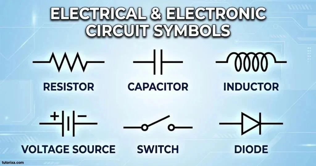
If you need a larger reference collection, this section provides more than 100 electrical and electronic circuit symbols by name, along with their basic functions.
The list includes common components used in educational diagrams, electronic projects, power systems, and industrial control circuits.
| No. | Circuit symbol name | Main function |
| 1 | Resistor | Limits current |
| 2 | Variable resistor | Changes resistance |
| 3 | Potentiometer | Adjusts voltage |
| 4 | Rheostat | Controls current |
| 5 | Thermistor | Senses temperature |
| 6 | Light-dependent resistor | Senses light |
| 7 | Fixed capacitor | Stores charge |
| 8 | Polarized capacitor | Stores charge with polarity |
| 9 | Variable capacitor | Adjusts capacitance |
| 10 | Trimmer capacitor | Fine-tunes capacitance |
| 11 | Air-core inductor | Stores magnetic energy |
| 12 | Iron-core inductor | Provides inductance |
| 13 | Ferrite-core inductor | Provides inductance |
| 14 | Transformer | Transfers electrical energy |
| 15 | Autotransformer | Changes AC voltage |
| 16 | Current transformer | Measures AC current |
| 17 | Potential transformer | Measures voltage |
| 18 | Crystal resonator | Stabilizes frequency |
| 19 | Varistor | Limits voltage surges |
| 20 | Fuse | Protects against overcurrent |
| 21 | Resettable fuse | Resets after a fault condition |
| 22 | Circuit breaker | Interrupts excessive current |
| 23 | Thermal fuse | Opens at a specified temperature |
| 24 | Single cell | Supplies DC voltage |
| 25 | Battery | Supplies electrical energy |
| 26 | DC voltage source | Provides DC voltage |
| 27 | AC voltage source | Provides AC voltage |
| 28 | Current source | Supplies specified current |
| 29 | Ground | Provides a reference point |
| 30 | Earth connection | Represents earth grounding |
| 31 | Chassis ground | Connects to equipment chassis |
| 32 | Protective earth | Provides a safety connection |
| 33 | Connecting wire | Connects circuit components |
| 34 | Junction | Shows connected wires |
| 35 | Crossing conductors | Shows crossing wire paths |
| 36 | Terminal | Provides a connection point |
| 37 | Connector | Joins electrical connections |
| 38 | Diode | Controls current direction |
| 39 | Zener diode | Regulates voltage |
| 40 | Schottky diode | Provides fast switching |
| 41 | Tunnel diode | Provides negative resistance |
| 42 | LED | Produces light |
| 43 | Photodiode | Detects light |
| 44 | Laser diode | Produces laser light |
| 45 | Varactor diode | Provides variable capacitance |
| 46 | Rectifier diode | Converts AC to DC |
| 47 | NPN transistor | Amplifies or switches signals |
| 48 | PNP transistor | Amplifies or switches signals |
| 49 | N-channel MOSFET | Controls current electronically |
| 50 | P-channel MOSFET | Controls current electronically |
| 51 | N-channel JFET | Controls current through a channel |
| 52 | P-channel JFET | Controls current through a channel |
| 53 | Darlington transistor | Provides high current gain |
| 54 | Phototransistor | Detects light |
| 55 | Unijunction transistor | Provides triggering functions |
| 56 | SCR | Controls current in one direction |
| 57 | TRIAC | Controls AC current |
| 58 | DIAC | Triggers bidirectional switching |
| 59 | Optocoupler | Provides electrical isolation |
| 60 | Integrated circuit | Performs multiple functions |
| 61 | Operational amplifier | Amplifies voltage differences |
| 62 | Comparator | Compares two voltage levels |
| 63 | AND gate | Requires all inputs to be high |
| 64 | OR gate | Responds when an input is high |
| 65 | NOT gate | Inverts a signal |
| 66 | NAND gate | Inverts AND logic |
| 67 | NOR gate | Inverts OR logic |
| 68 | XOR gate | Produces exclusive OR output |
| 69 | XNOR gate | Produces exclusive NOR output |
| 70 | Buffer | Strengthens or isolates a signal |
| 71 | Schmitt trigger | Provides signal conditioning |
| 72 | Flip-flop | Stores one bit |
| 73 | Latch | Holds a logic state |
| 74 | Multiplexer | Selects an input signal |
| 75 | Demultiplexer | Routes an input signal |
| 76 | Counter | Counts electrical pulses |
| 77 | Oscillator | Generates periodic signals |
| 78 | Timer IC | Provides timing functions |
| 79 | Crystal oscillator | Generates a stable frequency |
| 80 | Antenna | Transmits or receives radio signals |
| 81 | Single-pole switch | Controls one circuit |
| 82 | Double-pole switch | Controls two poles |
| 83 | Push-button switch | Provides momentary control |
| 84 | Toggle switch | Provides manual switching |
| 85 | Rotary switch | Selects different connections |
| 86 | Slide switch | Changes circuit connections |
| 87 | Reed switch | Operates using a magnetic field |
| 88 | Limit switch | Detects mechanical position |
| 89 | Relay | Electrically operates contacts |
| 90 | Solid-state relay | Switches electronically |
| 91 | Contactor | Switches power circuits |
| 92 | Normally open contact | Remains open at rest |
| 93 | Normally closed contact | Remains closed at rest |
| 94 | Electric lamp | Produces light |
| 95 | Fluorescent lamp | Produces light |
| 96 | Electric bell | Produces ringing sound |
| 97 | Buzzer | Produces an audible tone |
| 98 | Loudspeaker | Produces audio |
| 99 | Microphone | Converts sound into an electrical signal |
| 100 | DC motor | Converts electricity into rotation |
| 101 | AC motor | Produces mechanical movement |
| 102 | Generator | Produces electrical energy |
| 103 | Alternator | Generates AC electricity |
| 104 | Ammeter | Measures current |
| 105 | Voltmeter | Measures voltage |
| 106 | Ohmmeter | Measures resistance |
| 107 | Wattmeter | Measures electrical power |
| 108 | Galvanometer | Detects small currents |
| 109 | Frequency meter | Measures frequency |
| 110 | Solar cell | Converts light into electricity |
Important: This is a reference list of 110 component names and functions, not 110 distinct Unicode characters. Most circuit symbols are graphical drawings made from lines, shapes, and component-specific markings rather than standalone text characters.
Electronic Circuit Symbols List
An electronic circuit symbols list is useful when you want to find a component quickly without reading a long explanation.
The following quick-reference list organizes common symbols by their component names. The descriptions indicate their usual graphical appearance.
Basic Symbols
| Symbol name | How to recognize it |
| Wire | Straight line |
| Connected wires | Lines meeting at a junction dot |
| Unconnected crossing wires | Crossing lines without a connection |
| Cell | One long and one short parallel line |
| Battery | Several long and short parallel lines |
| Ground | Three descending horizontal lines |
| Resistor | Zigzag or rectangle |
| Capacitor | Two parallel plates |
| Inductor | Coil-shaped line |
| Switch | Two contacts with a movable connection |
Semiconductor Symbols
| Symbol name | How to recognize it |
| Diode | Triangle-like diode arrangement with a cathode bar in simplified teaching drawings; use the standard diode graphic in schematics |
| LED | Diode with outward arrows |
| Photodiode | Diode with inward arrows |
| Zener diode | Diode with a modified cathode bar |
| NPN transistor | Transistor with outward emitter arrow |
| PNP transistor | Transistor with inward emitter arrow |
| MOSFET | Gate, channel, and source/drain terminals |
| SCR | Thyristor with a gate terminal |
| TRIAC | Bidirectional thyristor |
| DIAC | Bidirectional trigger device |
Electrical And Output Symbols
| Symbol name | How to recognize it |
| Motor | Circle marked M |
| Generator | Circle marked G |
| Lamp | Circle with a cross |
| Bell | Bell-shaped graphic |
| Buzzer | Sounder graphic |
| Speaker | Cone-shaped graphic |
| Fuse | Fuse-specific rectangular or other standard form |
| Relay | Coil and associated contacts |
| Ammeter | Circle marked A |
| Voltmeter | Circle marked V |
| Ohmmeter | Circle marked Ω |
You can use this list as a quick reference while studying circuit diagrams or identifying components in an electronic project.
Electronic Circuit Symbols Chart
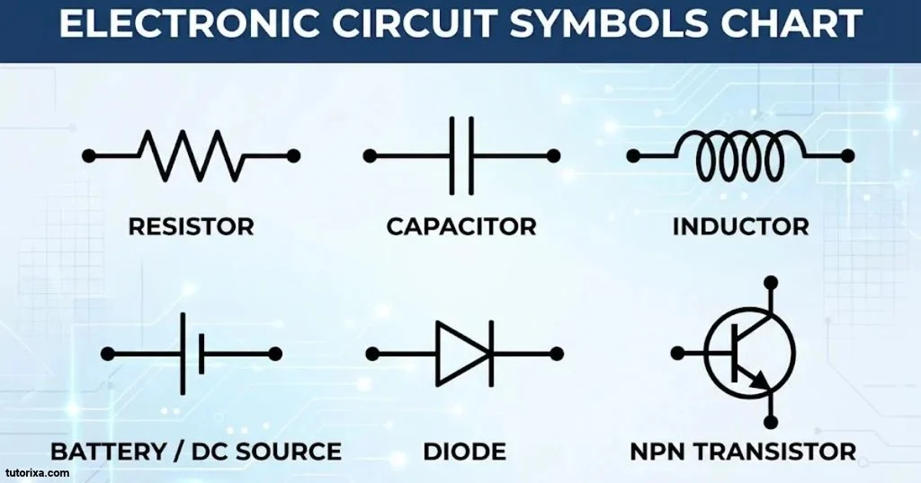
An electronic circuit symbols chart puts component drawings, names, and functions together in one place. It is especially helpful for students, beginners, technicians, and anyone who needs to understand a schematic.
A good chart should group similar components together instead of placing every symbol in a random order.
Basic Electronic Circuit Symbols Chart
| Component | Simplified representation | Function |
| Cell | Long and short parallel lines | Supplies voltage |
| Battery | Multiple cell pairs | Supplies electrical power |
| Resistor | Zigzag or rectangle | Limits current |
| Capacitor | Two parallel plates | Stores charge |
| Inductor | Coil | Stores magnetic energy |
| Diode | Diode with cathode bar | Controls current direction |
| LED | Diode with outward arrows | Produces light |
| Switch | Movable contact | Controls a circuit |
| Fuse | Fuse-specific graphic | Protects a circuit |
| Ground | Earth-style graphic | Provides a reference |
| Transformer | Two coil windings | Transfers AC energy |
| Transistor | Three-terminal symbol | Switches or amplifies |
| Motor | Circle marked M | Produces motion |
| Lamp | Circle with cross | Produces light |
| Bell | Bell-shaped graphic | Produces sound |
How To Read A Circuit Symbols Chart
Follow these simple steps when using a circuit symbols chart:
- Find the component you want to identify.
- Look at its graphical symbol.
- Read the component name beside it.
- Check its function to understand its role.
- Look for connection lines and terminal markings.
- Check the diagram legend if the symbol is unfamiliar.
Remember that a symbol’s appearance can change slightly depending on the drawing standard. Always use the correct chart for your project.
Electronic Circuit Symbols Diagram
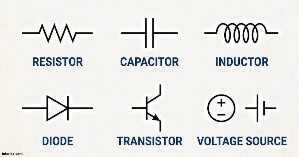
A circuit diagram uses symbols and connecting lines to show how electronic components are arranged and connected.
Unlike a physical picture of an electronic device, a schematic focuses on electrical connections and circuit operation. This makes it easier to understand the design without showing the actual size or physical position of every component.
Example Of A Simple Electronic Circuit Diagram
Here is a basic representation of a battery-powered LED circuit:
Simple LED circuit
Simplified illustrative diagram. Component graphics are explanatory rather than a standards-compliant schematic.
Main Parts Of The Diagram
- Battery: Supplies electrical energy to the circuit.
- Resistor: Limits the current flowing through the LED.
- LED: Converts electrical energy into light.
- Connecting wires: Provide a path for current to flow between components.
This example demonstrates how several individual components work together in a simple electronic circuit.
Common Connection Rules
When reading circuit diagrams, pay attention to these details:
- A solid line usually represents a conductor or connecting wire.
- A dot at a wire junction generally indicates an electrical connection.
- Crossing lines without a junction generally indicate that the wires are not connected.
- Component labels identify individual parts.
- Plus and minus markings show polarity when relevant.
These details help prevent confusion when following complex circuit paths.
Electronic Circuit Symbols For PowerPoint
Electronic circuit symbols are useful in PowerPoint presentations, especially for engineering lessons, electronics projects, classroom lectures, and technical explanations.
Instead of describing every component with text, you can use its schematic symbol to make your slides easier to understand.
Useful Symbols For PowerPoint Slides
Consider including these common symbols in your presentation:
| Symbol or graphic | Presentation topic |
| Resistor | Resistance and current |
| Capacitor | Electrical charge |
| Battery | Power sources |
| Cell | Basic electricity |
| Diode | Semiconductor operation |
| LED | Electronic lighting |
| Transistor | Switching and amplification |
| Switch | Circuit control |
| Fuse | Circuit protection |
| Transformer | Voltage conversion |
| Ground | Electrical connections |
| Motor | Electrical machines |
| Bell | Sound-producing devices |
| Ammeter | Current measurement |
| Voltmeter | Voltage measurement |
Tips For Creating Circuit Symbol Slides
- Use clear, recognizable schematic drawings.
- Add component names directly below the symbols.
- Keep the same symbol style throughout the presentation.
- Use simple backgrounds with good contrast.
- Avoid placing too many components on one slide.
- Use arrows or connecting lines to explain circuit flow.
- Include a legend when showing several unfamiliar symbols.
Where To Get Circuit Symbols For PowerPoint
You can create circuit symbols using vector graphics, schematic design software, or drawing tools.
Some useful options include:
- Microsoft PowerPoint: Use lines, shapes, and connectors to create simple diagrams.
- diagrams.net: Create circuit-style diagrams using available shapes.
- KiCad: Create professional electronic schematics.
- Inkscape: Create and edit scalable symbol illustrations.
For technical presentations, vector graphics are usually a good choice because they remain clear when resized.
US Electronic Circuit Symbols
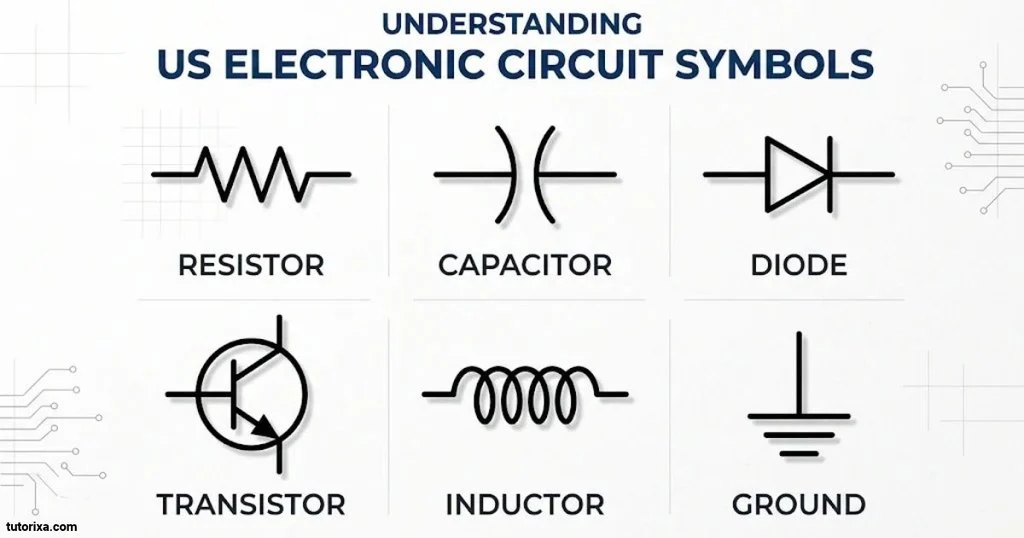
US electronic circuit symbols are commonly associated with the American schematic drawing tradition. They are used in electrical and electronic diagrams created for engineering, education, manufacturing, and industrial applications.
IEEE Std 315-1975, also published as ANSI Y32.2-1975, is an important historical reference for US electrical and electronic graphic symbols.
Many US symbols look similar to international IEC symbols, but some components have different graphical representations.
Common US Circuit Symbols
| Component | Common US representation | Function |
| Resistor | Zigzag line | Limits current |
| Capacitor | Two parallel plates | Stores charge |
| Polarized capacitor | Plates with polarity marking | Stores charge with polarity |
| Battery | Alternating long and short lines | Supplies energy |
| Cell | One long and one short line | Supplies voltage |
| Ground | Three descending lines | Reference connection |
| Switch | Movable contact | Opens or closes a circuit |
| Diode | Diode symbol with cathode bar | Controls current direction |
| LED | Diode with outward arrows | Produces light |
| Transistor | Three-terminal transistor symbol | Amplifies or switches signals |
| Inductor | Coil | Stores magnetic energy |
| Transformer | Two coils | Transfers electrical energy |
| Motor | Circle marked M | Produces mechanical motion |
US And IEC Symbol Differences
The two commonly encountered drawing traditions are the US IEEE/ANSI style and the international IEC style.
| Component | US convention | IEC convention |
| Resistor | Usually zigzag | Rectangle |
| Capacitor | Parallel plates | Parallel plates |
| Cell | Long and short lines | Long and short lines |
| Battery | Multiple cell pairs | Multiple cell pairs |
| Ground | Earth-style lines | Earth-style lines |
| Diode | Diode with cathode bar | Diode with cathode bar |
| Switch | Contact-based graphic | Contact-based graphic |
| Inductor | Coil | Coil |
The resistor is one of the easiest differences to recognize. US drawings traditionally use a zigzag line, while IEC drawings generally use a rectangular shape.
Both styles communicate the same electrical function. When working with a particular schematic, follow its specified standard and symbol legend rather than assuming every drawing uses the same conventions.
Battery Symbol Circuit
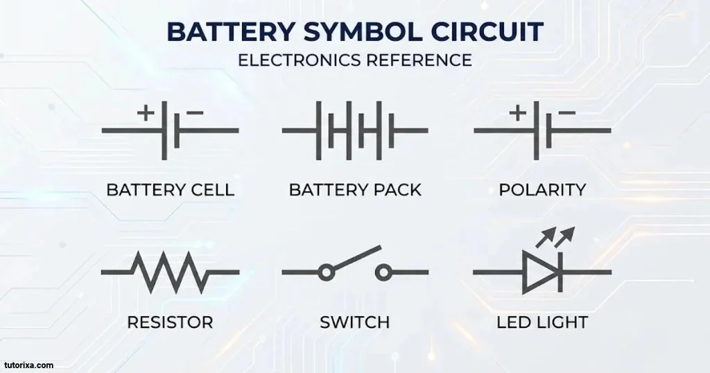
The battery symbol is one of the most recognizable symbols in electrical and electronic circuit diagrams. It represents a source of electrical energy that supplies voltage to connected components.
A standard battery symbol is made of alternating long and short parallel lines. The longer line represents the positive terminal, while the shorter line represents the negative terminal.
Battery symbol
Simplified two-cell battery representation.
What Does The Battery Symbol Mean?
The battery symbol indicates that a circuit receives electrical energy from a battery. It can represent different battery arrangements depending on the number of cell pairs shown.
Common applications include:
- Battery-powered toys.
- Remote controls.
- Flashlights.
- Portable electronic devices.
- Electronic learning projects.
- Backup power systems.
Battery Symbol Vs. Cell Symbol
A cell and a battery are related but not identical.
- A cell is a single electrochemical unit.
- A battery traditionally consists of two or more cells connected together.
- Both can supply electrical energy to a circuit.
The long and short lines help identify the terminals and polarity. The actual voltage is normally written beside the symbol when required.
Cell Symbol Circuit
A cell symbol represents a single electrical cell in a circuit diagram. It is generally drawn using two parallel lines of different lengths.
The longer line represents the positive terminal, and the shorter line represents the negative terminal.
Cell symbol
Simplified single-cell schematic symbol.
How Does A Cell Work In A Circuit?
A cell converts chemical energy into electrical energy through an electrochemical reaction. When connected to a suitable external circuit, it can drive an electric current.
Cells are commonly used in:
- Small electronic devices.
- Battery-powered clocks.
- Toys and remote controls.
- Portable measuring equipment.
- Educational circuit experiments.
Difference Between A Cell And A Battery
| Cell | Battery |
| Represents one electrochemical unit | Traditionally represents multiple cells |
| Uses one long and one short line | Uses multiple pairs of lines |
| Supplies electrical energy | Supplies electrical energy |
| Can be used alone | Can contain connected cells |
In everyday product descriptions, the word battery is also used for a single packaged cell, so terminology can depend on the context.
Conductor Symbol Circuit
A conductor symbol represents a wire or conductive path that allows electrical current to travel between components in a circuit.
It is usually drawn as a simple straight line. Conductors are essential because they connect the battery, resistors, switches, and other components.
Conductor symbol
A straight line represents a conductor or connecting wire in a basic schematic.
Different Conductor Connection Types
Not every line crossing in a circuit diagram means that the wires are connected. Understanding the different arrangements is important.
| Connection type | Representation | Meaning |
| Single conductor | Straight line | One conductive path |
| Connected conductors | Lines meeting with a dot | Wires are electrically joined |
| Unconnected crossing | Crossing lines without a junction dot | Wires are not connected |
| Multiple conductors | Several parallel lines | Separate conductive paths |
| Cable | Grouped conductor representation | Multiple wires in one cable |
| Junction | Connected lines with a node | Shared electrical connection |
Why Is The Conductor Symbol Important?
A conductor connects different components and provides a path for electrical current.
For example, in a simple battery and lamp circuit, conductors connect the battery terminals to the lamp so that the circuit can operate.
When reading more complicated diagrams, always check the junction dots and crossing arrangements carefully.
Electronic Circuit Symbols Bell
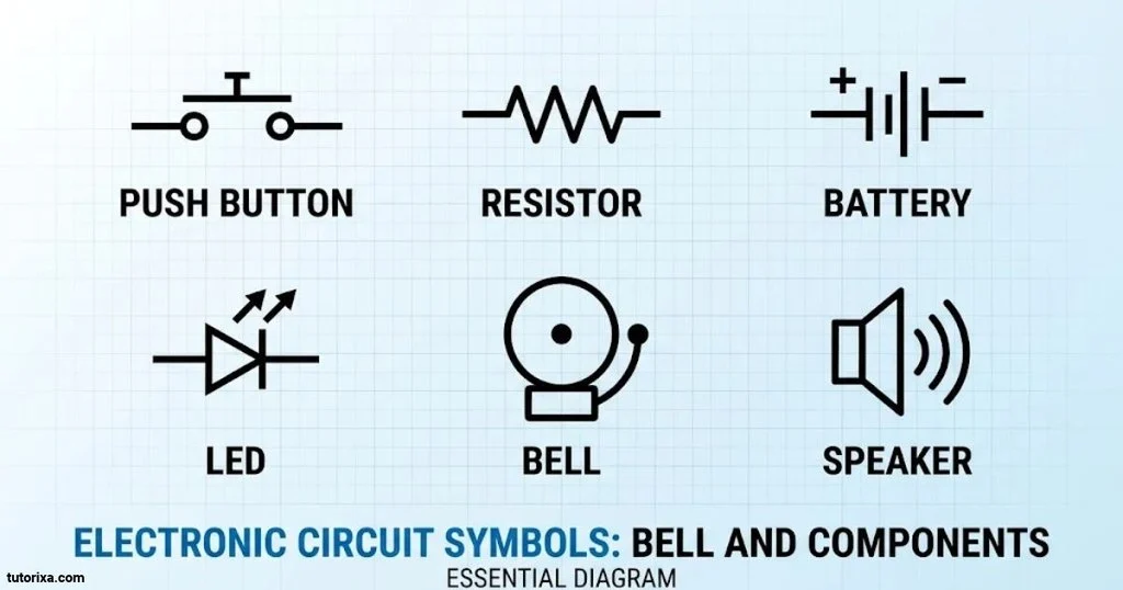
An electric bell symbol represents a sound-producing device used in electrical and electronic circuits. It is used to show a component that creates a ringing sound when activated.
An electric bell generally works through an electromagnetic mechanism. When electrical current energizes its coil, the mechanism moves a striker that hits a bell or gong.
Electric bell symbol
Illustrative reference for an electric bell graphic. The exact schematic representation depends on the drawing standard.
How Does An Electric Bell Work?
An electric bell typically works through the following process:
- A switch or push button completes the circuit.
- Electrical current flows through the bell’s electromagnetic coil.
- The electromagnet attracts a moving armature.
- A striker hits the bell or gong.
- The mechanism may repeatedly make and break the circuit to produce a ringing sound.
Common Uses Of Electric Bell Symbols
Electric bell symbols can appear in diagrams for:
- Doorbell systems.
- School bell systems.
- Alarm circuits.
- Industrial warning systems.
- Electrical control panels.
- Electronic learning projects.
Electric Bell Vs. Buzzer Symbol
An electric bell and a buzzer both produce sound, but they do not necessarily use the same mechanism.
| Electric bell | Buzzer |
| Commonly produces a ringing sound | Commonly produces a buzzing tone |
| May use a striker and gong | May use an electromagnetic or electronic sound mechanism |
| Often found in doorbell circuits | Often found in alarms and electronic devices |
| Uses a bell-specific graphic | Uses a buzzer or sounder graphic |
Do not treat every bell and buzzer symbol as interchangeable. Use the symbol shown in the relevant schematic standard or drawing legend.
Frequently Asked Questions
What Are Electronic Circuit Symbols?
Electronic circuit symbols are graphical representations of electrical and electronic components. They help people understand how components are connected and how a circuit operates without drawing the actual physical parts.
How Many Electronic Circuit Symbols Are There?
There are hundreds of commonly used electrical and electronic circuit symbols, with larger standards covering many specialized components and functions. The exact number depends on the standard and the types of diagrams included.
What Is The Most Common Symbol In An Electronic Circuit?
Resistors, capacitors, batteries, switches, diodes, and ground connections are among the most commonly encountered symbols. Their frequency depends on the type of circuit being studied.
What Is The Difference Between Electrical And Electronic Symbols?
Electrical symbols commonly represent power equipment, wiring, motors, and control devices. Electronic symbols more often represent components such as transistors, capacitors, diodes, and integrated circuits. Many symbols are shared between both fields.
Which Standard Is Used For Electronic Circuit Symbols?
IEC 60617 is an important international reference for graphical symbols used in electrical and electronic diagrams. IEEE Std 315-1975, also published as ANSI Y32.2-1975, is a historical reference for US drawing conventions. The appropriate standard depends on the project and industry.
Conclusion
Electronic circuit symbols provide a simple way to represent electrical and electronic components in diagrams. From basic resistors and capacitors to advanced transistors, integrated circuits, and power devices, each symbol helps explain the role of a component and its connection to the rest of the circuit.
Learning these symbols makes it easier to read schematics, understand electronic projects, and recognize different components. The symbol lists and charts in this guide can also serve as quick references for students, teachers, engineers, and electronics enthusiasts.
Start with the basic symbols and gradually learn the more specialized ones as you gain experience. Always check the applicable drawing standard when accuracy matters, especially when working with real electrical equipment.

I’m Rowan Whitaker, a British writer fascinated by the symbols surrounding us every day. I explore their meanings, origins, cultural significance, and changing interpretations. From ancient marks to modern signs, I enjoy making symbolism easier to understand. My writing helps curious readers discover the hidden messages behind familiar shapes, images, and signs.
Books:
- The Meaning Behind Symbols
- A Modern Guide to Symbolism
 Freddie Beaumont
 Ellis Montgomery